I took the Z3 down to the shop today to have the A/C lines evacuated and charged. I had to explain to the technician that was going to drive the car into the service bay how to operate the car. I wanted to make sure he was comfortable. There really is no trick to starting and driving it, but the lack of noise can throw people off.
After an hour and a half or so, the service rep came out to ask me if the oil that ships in the compressor has any dye in it. "Why, are you seeing dye?" They weren't, but he explained that the system was not holding a vacuum and they couldn't pin point the location of the leak. So they were thinking of putting some refrigerant in system to see if they could see the leak when it spit out colored stuff. The thing is, it's the oil in the systems they use that contain the dye when they want to track a leak, but we can't contaminate the MasterFlux system with standard oil for A/C units because it uses a special type of oil.
I asked them to do what they could to find the leak and moped back to my seat dreading having to take the system apart again. About 45 minutes later, the tech that drove the car into the service bay came back and asked me how much refrigerant they should put in the system. He explained that they'd put just under 2 lbs. in and it wasn't quite as cold as they like to see. Uh, what? I thought it wasn't sealing properly? He explained that it didn't under vacuum, but once they put refrigerant in the system, it seemed to be holding pressure just fine.
No one seemed to really know why this would be the case, or how something like this might happen. But the service rep hazarded a guess. He was thinking that the seals in the system may simply have been allowing air into the system when they were drawing the vacuum down because they'd dried out from the system being empty for so long, but once they turned the compressor on and the oil started flowing around the innards of the system, it may have lubricated the O-rings and helped them seat. Since no one had a better idea than that, we decided that must be it.
They put a thermometer in the vent and let the system run for several minutes to get a temperature reading of the out put. It read 60 °F. That is on the high end of normal. He noted that the high pressure side of the system had lower pressure than they're used to seeing. While I don't know this to be the case, my suspicion is that this system, which is designed to run between 120 and 420 VDC is operating at the low end of the scale in my car at only 160 V. So my guess is that it simply doesn't have the voltage behind it to drive it hard enough to get higher pressures.
In any event, the drive home was very pleasant. The compressor is pretty quiet. Standing over it while it's running, you hear a tick-tick-tick-tick sound, but its not particularly harsh or disturbing. Inside the car, I can feel it more than I can hear it. Well I can't really hear it from in the car, but I can feel it in my feet. Without it being mounted on those rubber bushings, I'm sure it would be very shaky indeed. All in all, I'm pleased. I would have liked another 10 °F temperature drop, but this is so much better than no A/C, I'm not complaining. I will be keeping an eye on it over the next few days, weeks, months to see if the output changes. I'm not convinced there's no leak just yet.
I also had them align the front end so that it has 0° toe-in. Normally cars are aligned with a slight 1 to 2° toe-in for tracking purposes. Without that, cars will tend to wander about the road, potentially following cracks or grooves in the pavement. Not a desirable trait really, but neither is an EV that uses more energy that in needs by scrubbing it off with the tires. As it turns out, they didn't have to adjust it much, and like I said yesterday, I really don't know if it's had an impact yet. On that note, I did receive the new 1/10 pre-scalar today, which will allow me to measure energy in and out again. Now I get to begin the long, arduous task of disassembling the passenger side dashboard.
Showing posts with label Air Conditioning. Show all posts
Showing posts with label Air Conditioning. Show all posts
Wednesday, September 14, 2011


Tuesday, September 13, 2011
On the Road Again
All Willie Nelson references aside, the Z3 is back on the road. There's a lot to tell, and I'm sorry I haven't posted more as I was working, but as most of you know, I have a deadline that I had to make. This made for some very long days and nights in the garage. I'll touch on some of the highlights, good and bad.
The controller for the MasterFlux compressor comes as a circuit board with an aluminum heat sink anchored to one side and all the components open to the world on the other side. You don't have to be a computer expert to know that probably ought to be protected from the elements. I started looking for a project box big enough to put it in and would fit in the space I had picked out for it, but found none. It wasn't long before I realized I was going to have to build my own. Well, I figured that would be fun. My material of choice would be thin sheets of aluminum, but I don't have a press break, or access to one. There was no way I was going to be able to build a nice box out of metal with neat edges.
OK, that meant plastic was the material of choice. I found someone on eBay selling sheets of PVC plastic, so I ordered a 2'x4' sheet. I was able to cut it quite easily with a utility knife and a metal straight edge. It was clearly formed with a PVC foam-like material rather than the type used to cast PVC joints for plumbing. But on thing was certain, it would glue the same. I very carefully cut sheets the proper size, planning on two sheets per side, sandwiched together, with staggered edges so I would have more surface area to make sturdier lap joints at the corners.
My plan to build a box around the controller was going well. But then my dad had a great suggestion. He noticed that the heat sink is a bit larger with the edges sticking out beyond the edges of the circuit board, so he suggested making that one side of the box and simply enclose the circuit board. Brilliant! I was able to do just that and build a secure mounting system and put it exactly where I had hoped I would be able to. This had the added benefit of leaving the heat sink open to the outside air for cooling

Notice the fins of the heat sink facing the front of the car between the two battery packs. Right next to that, to the left, is a little project box that holds a large diode and two relays. The diode is to prevent current from the capacitors on the controller board from flowing back into the car's traction system should the voltage in traction system drop below the voltage stored in those capacitors. Apparently this was a common problem with the MasterFlux units that they've decided to overcome by recommending you buy an extra $25 part. The relays work like this: the on/off switch on the car's dashboard for the A/C system triggers one relay, which provides power to the fan mounted on the condenser at the front of the car, and to the second relay. That second relay simply makes a contact that will allow the 5V signal back to the controller turning it on.
(By the way, notice the nice new braided connectors between the batteries. Nice huh? )
All of this should work flawlessly. In theory. You see, I tested what I could before hooking everything up, but there was no way to test all of it as one system after it was hooked up, until all the batteries were in. Plus, I have no idea if it's even safe to run the compressor before the system has been evacuated of air and charged. In fact, I've been trying to reach Revolt Electric (the resellers of MasterFlux products) to ask them about this and a few other things but they have been, how shall I say, less than diligent about returning emails or phone calls. Part of being a reseller is living up to the responsibility of offering end user support, and they're falling short at the moment.
Tomorrow morning, I'm taking the car into a local BMW shop to have them evacuate the system and charge it. First, they'll put a vacuum on the hoses and pump all the air out. They'll leave it like that for a couple hours to be sure it holds the vacuum. If it does it's good to charge. At this point I have no idea if it will. I can't express how much I hope it does, but there's no telling. Since one of the new joints in the system had a brazed fitting, I think that one will be fine. The other one was still an accursed compression fitting. I give it a 50% chance of holding a vacuum.
If it holds up they'll charge it and I get to turn it on for the first time. I'm not worried about incorrect wiring and/or damage to the system, but there is the distinct possibility that it simply won't work for some reason which I can't conceive of at the moment. I'm about 90% sure that will go well. Whether I drive out of the shop with A/C tomorrow, only time will tell.
They are also going to align the front end to take out all the toe-in. I never had it re-aligned, so it will be interesting to see how much of an impact this has on energy consumption. Sadly I won't know right away because the new meter I put in isn't working.
Actually, the meter is not the problem, it's the original pre-scalar I was using with the Link-10 meter. When I put power to the system yesterday, I turned on the meter and started running through the various menu setting to set it up for the car. When it was done, it read that the system voltage was 68.8V. Wha... I double checked that I'd selected the 1/10 pre-scalar knowing full well that I'd never seen a 1/4.3 setting that would be necessary to see 68.8 Volts. Eventually I pulled the meter out of the console and actually measured the voltage on the wires coming from the pre-scalar. I found that it read 6.88 volts. Well how about that. Apparently while the car sat doing nothing over the past 4 months, the pre-scalar developed some sort of problem that renders it useless. I have no idea how, or why, but a replacement unit is $54. *Sigh* A new one is on the way.
Astute readers will have noticed in the picture of the motor bay that the big red slap switch I had in the prior builds is gone. "Where did it go" you ask? Well after I pulled it out to start the work in the area, I noticed something peculiar about one of the contacts on the positive terminal side. Take a look:

You can see in the top right side what the contact pads should look like. They are little silver pads soldered on the copper bar. However in the bottom frames, you can see that one of them has completely melted away. The bottom left picture is the bottom bar in the contact, and the bottom right picture is it's mate above. At some point, there was some serious arcing in there that, for all intents and purposes, destroyed this switch. Well there was no way I was going to put it back like that, and I see no reason in replacing it with a like one as there will now be the possibility of sending even more current through it. Nope, I need to find some other safety disconnect. But, that will have to wait for later.
I finally added an expansion tank for the coolant used to keep the Zilla cool. Finding a location for it was a challenge. The fact is, it's on the opposite side of the car from where the pump is. As a result, there are coolant hoses running all over the place. The underside of the car is, quite frankly, a bit embarrassing now. It's just too crowded with stuff and it all looks a bit thrown together. Such is life. The cooling system does seem to work great though.

Yesterday after putting everything back in and together, I was working near one of the batteries while touching the chassis of the car, and I grazed a battery and felt an unmistakable shock. What the! My mind raced. I got out my meter to check and sure enough, there was continuity between the chassis and the battery pack. I stood there cursing, wondering how the hell that had happened. I disconnected the positive most terminal and started looking to see what had happened. Eventually I isolated the problem to the motor. My first though was that as I'd lowered the battery pack on top of the motor, I must have crushed one of the lugs and it shorted out to the motor's housing.
There was no way around it, that pack was going to have to come out. Mind you, this is coming less than an hour after I'd put the final bolt in holding everything together. What a bitter pill that was. Rather than take the pack out as a whole, I decided the best thing would be to dis-assemble the first row of batteries and remove them so that I could see the terminals which are under them and if I'd crushed a lug.
What I found was no crushed lugs, but one was clearly wedged in there and under pressure. I as able to get to it and get it out. I found that the plastic boot on the terminal had what amounts to a pressure wound on top of it and was actually pierced, ever so slightly. The heat shrink tube underneath it looked intact, but I cut if off and could clearly see a hole you could fit a pencil lead through when I held it up to the light. There it was, that was what had been touching the chassis. I found a less risky path for that wire and bolted all the wires back in place. I checked and there was no continuity. Problem fixed. Whew!
This morning, I re-assembled the rest of the system, put power to the system, dropped the car to the ground and carefully drove out of the garage. I took off down the road cautiously and found that the car was driving perfectly. Furthermore, the wobble that was in the drive line before it went up on blocks was now completely gone. The Warp 11 motor was perfect again. Finally, on the road again.
Tomorrow is my appointment with the shop, which I'll report on. The rest of the week will be spent replacing that pre-scalar, and getting ready to trailer the car and tow it to Missouri for EVCCON. I am genuinely looking forward to that.
The controller for the MasterFlux compressor comes as a circuit board with an aluminum heat sink anchored to one side and all the components open to the world on the other side. You don't have to be a computer expert to know that probably ought to be protected from the elements. I started looking for a project box big enough to put it in and would fit in the space I had picked out for it, but found none. It wasn't long before I realized I was going to have to build my own. Well, I figured that would be fun. My material of choice would be thin sheets of aluminum, but I don't have a press break, or access to one. There was no way I was going to be able to build a nice box out of metal with neat edges.
OK, that meant plastic was the material of choice. I found someone on eBay selling sheets of PVC plastic, so I ordered a 2'x4' sheet. I was able to cut it quite easily with a utility knife and a metal straight edge. It was clearly formed with a PVC foam-like material rather than the type used to cast PVC joints for plumbing. But on thing was certain, it would glue the same. I very carefully cut sheets the proper size, planning on two sheets per side, sandwiched together, with staggered edges so I would have more surface area to make sturdier lap joints at the corners.
My plan to build a box around the controller was going well. But then my dad had a great suggestion. He noticed that the heat sink is a bit larger with the edges sticking out beyond the edges of the circuit board, so he suggested making that one side of the box and simply enclose the circuit board. Brilliant! I was able to do just that and build a secure mounting system and put it exactly where I had hoped I would be able to. This had the added benefit of leaving the heat sink open to the outside air for cooling

Notice the fins of the heat sink facing the front of the car between the two battery packs. Right next to that, to the left, is a little project box that holds a large diode and two relays. The diode is to prevent current from the capacitors on the controller board from flowing back into the car's traction system should the voltage in traction system drop below the voltage stored in those capacitors. Apparently this was a common problem with the MasterFlux units that they've decided to overcome by recommending you buy an extra $25 part. The relays work like this: the on/off switch on the car's dashboard for the A/C system triggers one relay, which provides power to the fan mounted on the condenser at the front of the car, and to the second relay. That second relay simply makes a contact that will allow the 5V signal back to the controller turning it on.
(By the way, notice the nice new braided connectors between the batteries. Nice huh? )
All of this should work flawlessly. In theory. You see, I tested what I could before hooking everything up, but there was no way to test all of it as one system after it was hooked up, until all the batteries were in. Plus, I have no idea if it's even safe to run the compressor before the system has been evacuated of air and charged. In fact, I've been trying to reach Revolt Electric (the resellers of MasterFlux products) to ask them about this and a few other things but they have been, how shall I say, less than diligent about returning emails or phone calls. Part of being a reseller is living up to the responsibility of offering end user support, and they're falling short at the moment.
Tomorrow morning, I'm taking the car into a local BMW shop to have them evacuate the system and charge it. First, they'll put a vacuum on the hoses and pump all the air out. They'll leave it like that for a couple hours to be sure it holds the vacuum. If it does it's good to charge. At this point I have no idea if it will. I can't express how much I hope it does, but there's no telling. Since one of the new joints in the system had a brazed fitting, I think that one will be fine. The other one was still an accursed compression fitting. I give it a 50% chance of holding a vacuum.
If it holds up they'll charge it and I get to turn it on for the first time. I'm not worried about incorrect wiring and/or damage to the system, but there is the distinct possibility that it simply won't work for some reason which I can't conceive of at the moment. I'm about 90% sure that will go well. Whether I drive out of the shop with A/C tomorrow, only time will tell.
They are also going to align the front end to take out all the toe-in. I never had it re-aligned, so it will be interesting to see how much of an impact this has on energy consumption. Sadly I won't know right away because the new meter I put in isn't working.
Actually, the meter is not the problem, it's the original pre-scalar I was using with the Link-10 meter. When I put power to the system yesterday, I turned on the meter and started running through the various menu setting to set it up for the car. When it was done, it read that the system voltage was 68.8V. Wha... I double checked that I'd selected the 1/10 pre-scalar knowing full well that I'd never seen a 1/4.3 setting that would be necessary to see 68.8 Volts. Eventually I pulled the meter out of the console and actually measured the voltage on the wires coming from the pre-scalar. I found that it read 6.88 volts. Well how about that. Apparently while the car sat doing nothing over the past 4 months, the pre-scalar developed some sort of problem that renders it useless. I have no idea how, or why, but a replacement unit is $54. *Sigh* A new one is on the way.
Astute readers will have noticed in the picture of the motor bay that the big red slap switch I had in the prior builds is gone. "Where did it go" you ask? Well after I pulled it out to start the work in the area, I noticed something peculiar about one of the contacts on the positive terminal side. Take a look:

You can see in the top right side what the contact pads should look like. They are little silver pads soldered on the copper bar. However in the bottom frames, you can see that one of them has completely melted away. The bottom left picture is the bottom bar in the contact, and the bottom right picture is it's mate above. At some point, there was some serious arcing in there that, for all intents and purposes, destroyed this switch. Well there was no way I was going to put it back like that, and I see no reason in replacing it with a like one as there will now be the possibility of sending even more current through it. Nope, I need to find some other safety disconnect. But, that will have to wait for later.
I finally added an expansion tank for the coolant used to keep the Zilla cool. Finding a location for it was a challenge. The fact is, it's on the opposite side of the car from where the pump is. As a result, there are coolant hoses running all over the place. The underside of the car is, quite frankly, a bit embarrassing now. It's just too crowded with stuff and it all looks a bit thrown together. Such is life. The cooling system does seem to work great though.

Yesterday after putting everything back in and together, I was working near one of the batteries while touching the chassis of the car, and I grazed a battery and felt an unmistakable shock. What the! My mind raced. I got out my meter to check and sure enough, there was continuity between the chassis and the battery pack. I stood there cursing, wondering how the hell that had happened. I disconnected the positive most terminal and started looking to see what had happened. Eventually I isolated the problem to the motor. My first though was that as I'd lowered the battery pack on top of the motor, I must have crushed one of the lugs and it shorted out to the motor's housing.
There was no way around it, that pack was going to have to come out. Mind you, this is coming less than an hour after I'd put the final bolt in holding everything together. What a bitter pill that was. Rather than take the pack out as a whole, I decided the best thing would be to dis-assemble the first row of batteries and remove them so that I could see the terminals which are under them and if I'd crushed a lug.
What I found was no crushed lugs, but one was clearly wedged in there and under pressure. I as able to get to it and get it out. I found that the plastic boot on the terminal had what amounts to a pressure wound on top of it and was actually pierced, ever so slightly. The heat shrink tube underneath it looked intact, but I cut if off and could clearly see a hole you could fit a pencil lead through when I held it up to the light. There it was, that was what had been touching the chassis. I found a less risky path for that wire and bolted all the wires back in place. I checked and there was no continuity. Problem fixed. Whew!
This morning, I re-assembled the rest of the system, put power to the system, dropped the car to the ground and carefully drove out of the garage. I took off down the road cautiously and found that the car was driving perfectly. Furthermore, the wobble that was in the drive line before it went up on blocks was now completely gone. The Warp 11 motor was perfect again. Finally, on the road again.
Tomorrow is my appointment with the shop, which I'll report on. The rest of the week will be spent replacing that pre-scalar, and getting ready to trailer the car and tow it to Missouri for EVCCON. I am genuinely looking forward to that.
Tuesday, August 30, 2011
The A/C Lines Are Installed
I confess, I expected that getting the A/C lines made to hook up to this compressor was going to be a challenge. You could even say I was pessimistic about the whole affair. I just couldn't envision how these lines could be made to fit in place, tie seamlessly into the car's existing system and hold pressure. For a while it looked as if my doubts were justified.
When I got the hoses back toward the end of last week, the technician handed them to me and began to explain how I should hook them up. He said I should hook both ends up first, and then tighten the compression fitting in the middle. I felt a wave of panic when he said "compression fitting." You see, I hate compression fittings. Despise them. If there's a hell, it's occupied by the man that invented them and everyone else who is there is forever forced to try and make them work. It's been my experience that compression fittings work absolutely fine, until you try to put anything in the hose they are on under pressure. Then they proceed to leak everywhere, and nothing you do can makes them work.
I hooked up the long, low pressure line that runs from the evaporator to the compressor, and began carefully tightening the compression fittings. For those of you unfamiliar with how to tighten them, you are supposed to tighten them hand tight and then give the nut another 1/2 turn or so. If you under tighten it, it leaks. If you over tighten it, it leaks and you've ruined the ferrule inside and must replace it or the whole thing. With that in mind, I followed the rules: hand tight, but then I did about a 1/4 turn. I did a pressure test and it leaked like mad. OK, 1/4 more of a turn and another pressure test. More leaking. *Sigh* 1/4 more of a turn and it's leaking worse than ever. Undo the whole thing, check for dirt, debris or any other problems. It all seems fine, so try it again.
This went on for 3 hours or so. It began to become difficult working through the tears of anger and frustration. Eventually I had to resign myself to the fact that it simply wasn't going to work. Oddly, the second hose, the high pressure side, seemed to work just fine. Now I say that having not had the system charged. I fully expect that when I take it down to have the shop draw a vacuum on it, and then charge it up, they're going to tell me it leaks from that joint. I sure hope not, but if one of them is going to leak, that's the one that I can deal with. I can reach it and remove it without dis-assembling the car. The low pressure side requires I remove the larger battery rack under the hood to access it.
I took it back to the shop today and explained my problem. One of the guys, who's clearly been in this game for a while, looked at it and said, "Yeah, that will never seal. It needs to be brazed." That was music to my ears. He said give us a few minutes and we'll take care of it. They brazed a nut fitting on the aluminum tube and crimped it's male counter part on the existing hose. I was a little irritated that I'd spent all that time on a fitting that clearly the expert felt was the wrong part for the job. But I was so happy that it now had the right joint, I wasn't about to complain.

I took the parts back home and began hooking them up. It took a couple hours and I got the new dryer/receiver in place, both new hoses, the compressor mounted and the new lines attached to the compressor. It looks terrific, but I have no way of pressure testing it apart from adding coolant to the system, which I'm not going to do until I know it won't leak. Once the rest of the car is assembled, I'll drive it down to a local shop and they'll do all that for me.
I put together another quick (and very rough) video of what was accomplished today. Take a look...
Another component to this is the controls for the A/C system. They consist of an On/Off switch and a potentiometer that acts as the thermostat. MasterFlux sells a little black box that incorporates both of those items, but I can't imagine using that in the car because it's simply hideous. They say it's mostly for testing, and I can believe that. I picked one up in case I needed it, but I don't think I will, so it's going back. Instead, MasterFlux publish the specs on the device complete with part numbers and how to wire it. I found the very same potentiometer online and bought it. The great thing was they also had a variety of knobs to choose from to mount on the potentiometer's shaft, as well as the molex connector needed to plug all the wires into the controller board. For the On/Off switch I'll be using the original A/C On/Off switch that came with the car. Here's how the whole thing came out.

Down low on the center console, just the right of the gear shift is the little silver knob that will be the temperature control for the system. I really could think of no way to incorporate that functionality into the car's original thermostat dial above. You see that dial just moves different baffles to control the direction of air flow, either over the A/C system's evaporator, or over the heating core. There's no way to hook any electrical component up it. At least no way I was willing to try. I think that little knob will do just fine. The On/Off switch is the top button in that two button module directly to the right of the new Link-Pro meter.
Lastly, you may recall that I was having problems keeping the Zilla controller cool in the desert heat. I think part of the problem was the fact that I was using a radiator that was only 4"x8" in size. Well in the video above, you saw that the new radiator is about 3 times that size. Hopefully it will keep things a bit cooler. But it also has a nice big fan to help suck air through it. Well, I didn't see any point to having that fan run all the time. After all, when I'm sitting idle in traffic, there's no heat generated in the Zilla, or when I'm cruising down the road at 40 MPH drawing only 60 amps, the air moving through the radiator is more than adequate to cool the controller.
What I need is some way to monitor the temperature of the controller and turn the fan on when it starts to get too warm. I started looking and found what I think would work. It's a switch that will close a contact when it hits 122 °F. It opens up again at around 115°. That is well below the point the Zilla begins to complain about heat, but high enough that the fan won't run unnecessarily. The switch itself is just a little button style switch that has to be in contact with the item you're monitoring. The place I've noticed seems to get hottest on the Zilla is the top, right in the center. It may get hotter else where, but I don't have access to where ever that might be. So the question became, how do I mount a small dime-sized switch to the top of the Zilla without it moving around or looking too hideous. Here's what I came up with, you be the judge...

That piece of aluminum is pressed and held down tight to the top of the controller. The switch is held down tight to the aluminum strip. I used some thermal paste left over from my last CPU purchase to help heat conduct into the switch. The switch drives the relay you see at the bottom of the screen, which will then turn the fan for the radiator on. OK, it might not be the sexiest of solutions, but I thought it was pretty clever and should do the trick nicely.
When I got the hoses back toward the end of last week, the technician handed them to me and began to explain how I should hook them up. He said I should hook both ends up first, and then tighten the compression fitting in the middle. I felt a wave of panic when he said "compression fitting." You see, I hate compression fittings. Despise them. If there's a hell, it's occupied by the man that invented them and everyone else who is there is forever forced to try and make them work. It's been my experience that compression fittings work absolutely fine, until you try to put anything in the hose they are on under pressure. Then they proceed to leak everywhere, and nothing you do can makes them work.
I hooked up the long, low pressure line that runs from the evaporator to the compressor, and began carefully tightening the compression fittings. For those of you unfamiliar with how to tighten them, you are supposed to tighten them hand tight and then give the nut another 1/2 turn or so. If you under tighten it, it leaks. If you over tighten it, it leaks and you've ruined the ferrule inside and must replace it or the whole thing. With that in mind, I followed the rules: hand tight, but then I did about a 1/4 turn. I did a pressure test and it leaked like mad. OK, 1/4 more of a turn and another pressure test. More leaking. *Sigh* 1/4 more of a turn and it's leaking worse than ever. Undo the whole thing, check for dirt, debris or any other problems. It all seems fine, so try it again.
This went on for 3 hours or so. It began to become difficult working through the tears of anger and frustration. Eventually I had to resign myself to the fact that it simply wasn't going to work. Oddly, the second hose, the high pressure side, seemed to work just fine. Now I say that having not had the system charged. I fully expect that when I take it down to have the shop draw a vacuum on it, and then charge it up, they're going to tell me it leaks from that joint. I sure hope not, but if one of them is going to leak, that's the one that I can deal with. I can reach it and remove it without dis-assembling the car. The low pressure side requires I remove the larger battery rack under the hood to access it.
I took it back to the shop today and explained my problem. One of the guys, who's clearly been in this game for a while, looked at it and said, "Yeah, that will never seal. It needs to be brazed." That was music to my ears. He said give us a few minutes and we'll take care of it. They brazed a nut fitting on the aluminum tube and crimped it's male counter part on the existing hose. I was a little irritated that I'd spent all that time on a fitting that clearly the expert felt was the wrong part for the job. But I was so happy that it now had the right joint, I wasn't about to complain.

I took the parts back home and began hooking them up. It took a couple hours and I got the new dryer/receiver in place, both new hoses, the compressor mounted and the new lines attached to the compressor. It looks terrific, but I have no way of pressure testing it apart from adding coolant to the system, which I'm not going to do until I know it won't leak. Once the rest of the car is assembled, I'll drive it down to a local shop and they'll do all that for me.
I put together another quick (and very rough) video of what was accomplished today. Take a look...
Another component to this is the controls for the A/C system. They consist of an On/Off switch and a potentiometer that acts as the thermostat. MasterFlux sells a little black box that incorporates both of those items, but I can't imagine using that in the car because it's simply hideous. They say it's mostly for testing, and I can believe that. I picked one up in case I needed it, but I don't think I will, so it's going back. Instead, MasterFlux publish the specs on the device complete with part numbers and how to wire it. I found the very same potentiometer online and bought it. The great thing was they also had a variety of knobs to choose from to mount on the potentiometer's shaft, as well as the molex connector needed to plug all the wires into the controller board. For the On/Off switch I'll be using the original A/C On/Off switch that came with the car. Here's how the whole thing came out.

Down low on the center console, just the right of the gear shift is the little silver knob that will be the temperature control for the system. I really could think of no way to incorporate that functionality into the car's original thermostat dial above. You see that dial just moves different baffles to control the direction of air flow, either over the A/C system's evaporator, or over the heating core. There's no way to hook any electrical component up it. At least no way I was willing to try. I think that little knob will do just fine. The On/Off switch is the top button in that two button module directly to the right of the new Link-Pro meter.
Lastly, you may recall that I was having problems keeping the Zilla controller cool in the desert heat. I think part of the problem was the fact that I was using a radiator that was only 4"x8" in size. Well in the video above, you saw that the new radiator is about 3 times that size. Hopefully it will keep things a bit cooler. But it also has a nice big fan to help suck air through it. Well, I didn't see any point to having that fan run all the time. After all, when I'm sitting idle in traffic, there's no heat generated in the Zilla, or when I'm cruising down the road at 40 MPH drawing only 60 amps, the air moving through the radiator is more than adequate to cool the controller.
What I need is some way to monitor the temperature of the controller and turn the fan on when it starts to get too warm. I started looking and found what I think would work. It's a switch that will close a contact when it hits 122 °F. It opens up again at around 115°. That is well below the point the Zilla begins to complain about heat, but high enough that the fan won't run unnecessarily. The switch itself is just a little button style switch that has to be in contact with the item you're monitoring. The place I've noticed seems to get hottest on the Zilla is the top, right in the center. It may get hotter else where, but I don't have access to where ever that might be. So the question became, how do I mount a small dime-sized switch to the top of the Zilla without it moving around or looking too hideous. Here's what I came up with, you be the judge...

That piece of aluminum is pressed and held down tight to the top of the controller. The switch is held down tight to the aluminum strip. I used some thermal paste left over from my last CPU purchase to help heat conduct into the switch. The switch drives the relay you see at the bottom of the screen, which will then turn the fan for the radiator on. OK, it might not be the sexiest of solutions, but I thought it was pretty clever and should do the trick nicely.
Wednesday, August 17, 2011
Mounting the Compressor
The last two weeks have been exceedingly busy and it's only been these last two days that I've actually had the opportunity to begin working on the car again. Very frustrating! But I've made some progress, and I thought I'd share what's been done.
I finished building and installing the motor mount, which meant that I could finish making all the connections to the transmission; drive shaft, clutch slave cylinder, gear shift linkage, and reverse light connection. Incidentally, I was able to find the proper Bosch female connector to go with the male connector used for the reverse light switch mounted to the transmission. That was not an easy item to locate. To make it worse, apparently Bosch only manufactures them in lots once every so often because they were unavailable at every place that carried them for months, and then in a weeks time everyone had them.
At any rate, the drive line is complete, and the motor is safely tied down. It is resting on and held down to a solid piece of hard rubber designed for motor mounts. The original cross members that prevent the motor from spinning while under torque are still there, but I've added some rubber cushioning that will absorb shocks from upward travel as well. So to recap, I have hard rubber pads set to absorb any vertical bumps or vibration, and braces to keep the motor from spinning. It's not going anywhere, and it should be nicely isolated from any sharp bumps the chassis receives.
The last couple days I finished building the tray and the supports that will hold the MasterFlux A/C compressor. It's a tricky fit, just like everything else in the car. It will be suspended from the front battery tray as mentioned in previous posts, but it can't be directly under, or there would be no room to hook the pressurized coolant lines up. So it has to hang below and slightly behind the rack. Maybe a video will demonstrate it a bit better. Take a look.
I'm not sure that the shaky camera and rambling dialogue help clear things up, but hopefully you get an idea of what's involved. Afterward, I took some careful measurements of where the new hoses needed to run, and disconnected the existing hoses. I took them down to a local shop and explained what I need. I was worried that they'd want to finish the hoses on the first visit, and I'd run into problems when tying to put them in the car. Not only do the hoses need to be the correct length, but the new fittings that I need for the new compressor have to be crimped on at the proper angle so there's no twist in the lines. Apparently this is not an uncommon problem.
What they intend to do is cut the old hoses off the fitting end that I need to keep and crimp new hoses on that are a bit longer than I need. Then they'll call me in and hand me the half completed hoses and the new fittings. I can then bring the whole lot home and mount it up, cut the hose to length and mark the proper angle to crimp the new fittings on and return it to them for the final crimp. Of course I still need to find a place to mount the compressor's controller and all the supporting electronics. Truthfully, that has me worried. I have an idea of where it might go, but I won't know for certain if it will fit in that space until both battery racks are mounted back in the car.
With the addition of the new meter, and it's larger shunt, I thought I'd take this opportunity to hook things up in a cleaner way. The old set up had all of the negative lines from the high voltage side running to one side of the shunt. There was the 2/0 cable from the controller, the 6 AWG from the charger, a 10 AWG from the heater core, a 12 AWG for the DC to DC converter and a small 18 AWG for the negative lead to the meter. That's a lot so squeeze onto one terminal. So instead, I'm adding a bus bar. The bus bar I got has 4 leads, three of which will hold all those cables and wires mentioned above, and the last remaining one will be reserved for a new cable that will run to the new shunt.
The only problem is that the bus is only rated for 400 amps. As we all know, I'm looking to put 1000 amps through it. Well the reason it's rated at 400 is that there is only one 1/8" thick piece of copper tying all the connectors together. To over come this, I've made 3 new strips of copper totaling 3/16" to stack on top of the existing one, for a total of 5/16" of copper. That is more than enough for 1000 amps. That's nearly twice the thickness of the battery straps.

Speaking of battery straps, I'm taking out the original copper straps that came with the Sky Energy (CALB) cells and replacing them with the braided copper straps from EV Works. While I'm at it, I've gotten rid of all the old washers and split ring washers in favor of Nord-Lock washers. These changes will allow for two things. First, as the chassis moves around and the batteries jostle about, those braided connections will flex the tiny amount needed and not put any strain on the connection point at each battery. This will help to ensure that there is always a good connection at each terminal. To further ensure a good connection, I'm using the Nord-Lock washers. Once you've tightened down a bolt with one of those washers on it, it does not back off. Vibration or the usual expansion and contraction due to temperature changes simply won't affect them. Consequently, no loose connections, no fires.
I finished building and installing the motor mount, which meant that I could finish making all the connections to the transmission; drive shaft, clutch slave cylinder, gear shift linkage, and reverse light connection. Incidentally, I was able to find the proper Bosch female connector to go with the male connector used for the reverse light switch mounted to the transmission. That was not an easy item to locate. To make it worse, apparently Bosch only manufactures them in lots once every so often because they were unavailable at every place that carried them for months, and then in a weeks time everyone had them.
At any rate, the drive line is complete, and the motor is safely tied down. It is resting on and held down to a solid piece of hard rubber designed for motor mounts. The original cross members that prevent the motor from spinning while under torque are still there, but I've added some rubber cushioning that will absorb shocks from upward travel as well. So to recap, I have hard rubber pads set to absorb any vertical bumps or vibration, and braces to keep the motor from spinning. It's not going anywhere, and it should be nicely isolated from any sharp bumps the chassis receives.
The last couple days I finished building the tray and the supports that will hold the MasterFlux A/C compressor. It's a tricky fit, just like everything else in the car. It will be suspended from the front battery tray as mentioned in previous posts, but it can't be directly under, or there would be no room to hook the pressurized coolant lines up. So it has to hang below and slightly behind the rack. Maybe a video will demonstrate it a bit better. Take a look.
I'm not sure that the shaky camera and rambling dialogue help clear things up, but hopefully you get an idea of what's involved. Afterward, I took some careful measurements of where the new hoses needed to run, and disconnected the existing hoses. I took them down to a local shop and explained what I need. I was worried that they'd want to finish the hoses on the first visit, and I'd run into problems when tying to put them in the car. Not only do the hoses need to be the correct length, but the new fittings that I need for the new compressor have to be crimped on at the proper angle so there's no twist in the lines. Apparently this is not an uncommon problem.
What they intend to do is cut the old hoses off the fitting end that I need to keep and crimp new hoses on that are a bit longer than I need. Then they'll call me in and hand me the half completed hoses and the new fittings. I can then bring the whole lot home and mount it up, cut the hose to length and mark the proper angle to crimp the new fittings on and return it to them for the final crimp. Of course I still need to find a place to mount the compressor's controller and all the supporting electronics. Truthfully, that has me worried. I have an idea of where it might go, but I won't know for certain if it will fit in that space until both battery racks are mounted back in the car.
With the addition of the new meter, and it's larger shunt, I thought I'd take this opportunity to hook things up in a cleaner way. The old set up had all of the negative lines from the high voltage side running to one side of the shunt. There was the 2/0 cable from the controller, the 6 AWG from the charger, a 10 AWG from the heater core, a 12 AWG for the DC to DC converter and a small 18 AWG for the negative lead to the meter. That's a lot so squeeze onto one terminal. So instead, I'm adding a bus bar. The bus bar I got has 4 leads, three of which will hold all those cables and wires mentioned above, and the last remaining one will be reserved for a new cable that will run to the new shunt.
The only problem is that the bus is only rated for 400 amps. As we all know, I'm looking to put 1000 amps through it. Well the reason it's rated at 400 is that there is only one 1/8" thick piece of copper tying all the connectors together. To over come this, I've made 3 new strips of copper totaling 3/16" to stack on top of the existing one, for a total of 5/16" of copper. That is more than enough for 1000 amps. That's nearly twice the thickness of the battery straps.

Speaking of battery straps, I'm taking out the original copper straps that came with the Sky Energy (CALB) cells and replacing them with the braided copper straps from EV Works. While I'm at it, I've gotten rid of all the old washers and split ring washers in favor of Nord-Lock washers. These changes will allow for two things. First, as the chassis moves around and the batteries jostle about, those braided connections will flex the tiny amount needed and not put any strain on the connection point at each battery. This will help to ensure that there is always a good connection at each terminal. To further ensure a good connection, I'm using the Nord-Lock washers. Once you've tightened down a bolt with one of those washers on it, it does not back off. Vibration or the usual expansion and contraction due to temperature changes simply won't affect them. Consequently, no loose connections, no fires.
Monday, August 1, 2011
The A/C System Has Arrived
Last week, the Masterflux A/C system arrived from Revolt Electric, a full 3 weeks ahead of the initial 6 week wait they said I was in for. Fantastic news and time to get cracking on mounting it. I opted for the Sierra Model 06-0982Y3, and the 025F0140-03 controller. The controller can be driven with anything from 120V to 420V DC, and the compressor is capable of putting out over 15,000 BTU. Of course, that's when it operates at over 300 V DC. Since my pack voltage is 160, it will be putting out roughly 10,000 BTU. Should be plenty adequate for a two-seater car that has slightly more cabin space than the inside of a microwave. At full power, it will draw about 6 amps, just shy of 1 kW.
First things first. In order to mount the A/C compressor, I need to know how much room I have to work with. It's going to fit right behind the condenser for the A/C system and the new radiator I'm installing for the Zilla. But before I could measure how much space I needed to build the frame that will hold radiator and then mount it in place. Here's a shot of the radiator in it's frame:
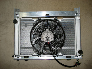
Essentially what I built is a frame made from various angle aluminum stock. The radiator doesn't have any screws or brackets that you can use to mount it to anything. All it has is three pegs meant to hold rubber bushings that would then be pushed into some mounting bracket. Try as I might, I could not find any bushings that would fit the posts. What I did find where rubber stoppers at the local hardware store. I bought three of them and drilled a hole through each. Then I constructed the frame, drilling holes to accept the "bushings" I made and then fastened the whole thing together. It turned out pretty well. The radiator is suspended in that frame via those bushings which provide a little shock absorption for the assembly. It will be suspended from the front battery rack by those two tabs you see sticking out of the top of the rack.
Once that was complete, I put the assembly in place and just clamped it so that I could start figuring out how to position the compressor. I was very worried that I'd have little to know extra room, but as it turns out, I have loads of space. I think there may be as much as a full inch in either direction for me to play with. That may not sound like much, but trust me, that is huge. I've had a difficult time fitting very nearly every component since I started the build, running short by 1/16th of an inch here or there was way to common. Very frustrating.
The A/C compressor will rest in a tray I've made, that will then be suspended from the front battery rack as well. Here is a shot of the tray I made today:

Notice the three large holes in the middle. They are for the rubber feet that hold the compressor, which cushion vibration while it's running. The tray is 1/8" aluminum plate surrounded by 1x1 inch aluminum angle stock. It is light yet remarkably stiff. The compressor weighs about 20 lbs, so it needs to be sturdy.
At this point, I'm very glad I made that rack out of steel. It will end up supporting 12 batteries, the power steering pump, the Zilla's radiator and the A/C compressor. Fortunately it's more than sturdy enough to support all that weight, as are the brackets it mounts to in the car.
My recent experience working with steel and aluminum for all the different support structures that I'm adding is not too dissimilar than my past experience. I've found that building an EV is an endeavor that requires a great deal of care and attention to detail. You decide how and where you're going to mount something, and measure the space. You measure even more carefully, and even build cardboard models. Then you begin cutting the metal you need. Once everything is cut, you start drilling and bolting and/or welding it into it's final shape. You then go back to fit it in the car, and discover that it won't work for some completely unexpected reason. So you scrap the whole thing and start over. Maybe it's just me, but this seems to be an ongoing theme.
Next I get to build the structure that this tray will be suspended from.
On a final note, I did finish installing the new Link-Pro meter in the car. It fit perfectly, replacing the Link-10 effortlessly. I still need to find a new place for that shunt, but I'm not too worried about that.
First things first. In order to mount the A/C compressor, I need to know how much room I have to work with. It's going to fit right behind the condenser for the A/C system and the new radiator I'm installing for the Zilla. But before I could measure how much space I needed to build the frame that will hold radiator and then mount it in place. Here's a shot of the radiator in it's frame:

Essentially what I built is a frame made from various angle aluminum stock. The radiator doesn't have any screws or brackets that you can use to mount it to anything. All it has is three pegs meant to hold rubber bushings that would then be pushed into some mounting bracket. Try as I might, I could not find any bushings that would fit the posts. What I did find where rubber stoppers at the local hardware store. I bought three of them and drilled a hole through each. Then I constructed the frame, drilling holes to accept the "bushings" I made and then fastened the whole thing together. It turned out pretty well. The radiator is suspended in that frame via those bushings which provide a little shock absorption for the assembly. It will be suspended from the front battery rack by those two tabs you see sticking out of the top of the rack.
Once that was complete, I put the assembly in place and just clamped it so that I could start figuring out how to position the compressor. I was very worried that I'd have little to know extra room, but as it turns out, I have loads of space. I think there may be as much as a full inch in either direction for me to play with. That may not sound like much, but trust me, that is huge. I've had a difficult time fitting very nearly every component since I started the build, running short by 1/16th of an inch here or there was way to common. Very frustrating.
The A/C compressor will rest in a tray I've made, that will then be suspended from the front battery rack as well. Here is a shot of the tray I made today:

Notice the three large holes in the middle. They are for the rubber feet that hold the compressor, which cushion vibration while it's running. The tray is 1/8" aluminum plate surrounded by 1x1 inch aluminum angle stock. It is light yet remarkably stiff. The compressor weighs about 20 lbs, so it needs to be sturdy.
At this point, I'm very glad I made that rack out of steel. It will end up supporting 12 batteries, the power steering pump, the Zilla's radiator and the A/C compressor. Fortunately it's more than sturdy enough to support all that weight, as are the brackets it mounts to in the car.
My recent experience working with steel and aluminum for all the different support structures that I'm adding is not too dissimilar than my past experience. I've found that building an EV is an endeavor that requires a great deal of care and attention to detail. You decide how and where you're going to mount something, and measure the space. You measure even more carefully, and even build cardboard models. Then you begin cutting the metal you need. Once everything is cut, you start drilling and bolting and/or welding it into it's final shape. You then go back to fit it in the car, and discover that it won't work for some completely unexpected reason. So you scrap the whole thing and start over. Maybe it's just me, but this seems to be an ongoing theme.
Next I get to build the structure that this tray will be suspended from.
On a final note, I did finish installing the new Link-Pro meter in the car. It fit perfectly, replacing the Link-10 effortlessly. I still need to find a new place for that shunt, but I'm not too worried about that.
Thursday, July 14, 2011
Now That's a Shunt!
There hasn't been a lot to report over the past few weeks. I've been dealing with acquiring the hardware necessary for the Air Conditioning system.
You may recall I'd ordered a Masterflux compressor and controller off a user on eBay for a bargain $200. The unit was reported to be new but old stock. In addition it required a 48 Volt DC supply. I'd been looking for how I was going to supply the necessary current to the controller at the proper voltage. Well the good news is that I've solved that problem, sort of. It turns out the compressor was not new, old stock. It was in fact used and not in good condition. The compressor had been crammed into the box along with two poorly protected controllers. Both had sustained damage while in shipment. Why the shipped two controllers, I have no idea.
Ultimately, I didn't trust either controller to work properly, and simply because of the circumstances, perhaps due to guilt by association, I didn't trust the compressor either. Everything went back.
Instead I have on order a brand new system that is designed to work directly off of my 160 volt DC system with no modifications required. The upside is obvious; the downside is it was $1200 more than the other system. Still, I'd rather spend the money and have a system that works. I don't want to mess with it once it's up and running.
In the mean time, I've been working on the revised motor mount. I cut and formed some steel and started dry fitting everything. Sadly I ran into another road block on this front. The problem I face is of course one of space. I need to get adequate shock absorption material under the motor. without any, it simply lays on the front steering rack with about 1/2" gap between the motor and the sub-frame right behind the steering rack. I need to support the motor so it's at least 1/4" off the rack so that it doesn't hit it during any vibration. More space would be better. The problem is that if I push the motor up too far, I begin to ruin the alignment of the drive line.
So, I need to find a way to support the motor in the proper position, with the proper attitude, provide shock absorption and tie it to the frame securely. I could go back with the previous solution I had, but I'd really like to add more shock absorbing material. The short story is that the pretty solution I drew up in the previous post simply won't work. Back to the drawing board.
I also started working on a minor part of the A/C system, and that was how to turn it on and off. The Z3 has a neat little button in the console with a picture of a snow flake on it. When you depress the button, it glows orange and turns on the A/C. I tried it out to make sure that it still sends a 12volt signal to the line that previously went to the compressor to turn it on, and no luck. I don't know if the ECU needed other connections from the wiring harness that are no longer there, but there was no way I could get that to power up.
Instead, I took the switch out, and started reverse engineering it. That switch also has the button to turn on/off air recirculation within the cabin. It has 8 points of connection. In short order I figured out which blade had power to it when all the right conditions were met; the A/C button was depressed, and the HVAC system fan was on. I simply spliced a new wire into that line so that I can draw 12V off it to power a new relay. That relay will turn on power to a fuse box that will provide power to the Masterflux controller and the AC condenser fan and a cooling fan for the controller itself.
I'm also taking this opportunity to swap out the Xantrex Link-10 meter I've been using, for a Xantrex Link-Pro. OK, it's actually the e-Xpert Pro; same thing. Why the change? You can chalk this up to a rookie mistake. In the beginning, when I was ordering all the parts for the car, I simply didn't understand how all of the component's specs needed to match up. I ordered a Zilla capable of putting out 1000 amps, and the Link-10 capable of reading only 500 amps. As long as I left the Zilla set to a 500 amp output or lower, then the Link-10 meter could measure the current accurately. If I set the Zilla higher, it didn't hurt the meter, but it simply didn't read the current, which meant the usage it reflected in terms of the battery's state of charge would be wrong.
Part of the package is a much bigger shunt, one that can handle 1000 amps vs. the 500 amp shunt for the old meter. Check it out...
 It reminds me of Crocodile Dundee, "that's not a knife..." That thing is huge! Which raises a concern as to where I'm going to put it. I think I'll be able to fit it where the old one was. I hope. Fortunately, the meter is exactly the same size and the leads I need to power it and provide data to it are identical, so it's a straight swap as far as that goes. I did opt for one other thing when I bought the meter, and that is a temperature sensor that I'll be running to one of the batteries. I'm going to pick one somewhere in the middle of the pack, one that is likely to get the warmest. In this way I can keep an eye on the temperature of the pack during the summer heat.
One other thing I've done was to remove the gaps between the batteries I have in the box under the trunk. I'd put gaps between them so that I could force air between them if necessary. I had installed a thermal switch that would turn on and force air over the batteries if they reached 125 °F. It never came on. Plus with the temperature monitoring I will now have on the meter, it's not really necessary. But the biggest reason is that I intend to replace all the copper straps that connected the batteries with braided ones. In order to do so, I need the batteries pushed together.
So, I pushed all the batteries together and then carefully measured and cut some wood to push into the space created. Mind you, this isn't to compress the cells, but merely to keep them from moving around.
 You can see it there over on the left hand side. As I'd mentioned before, and as several people have discovered, the cells do not expand unless you over charge or over drain the, rendering clamping them together unnecessary.
You may recall I'd ordered a Masterflux compressor and controller off a user on eBay for a bargain $200. The unit was reported to be new but old stock. In addition it required a 48 Volt DC supply. I'd been looking for how I was going to supply the necessary current to the controller at the proper voltage. Well the good news is that I've solved that problem, sort of. It turns out the compressor was not new, old stock. It was in fact used and not in good condition. The compressor had been crammed into the box along with two poorly protected controllers. Both had sustained damage while in shipment. Why the shipped two controllers, I have no idea.
Ultimately, I didn't trust either controller to work properly, and simply because of the circumstances, perhaps due to guilt by association, I didn't trust the compressor either. Everything went back.
Instead I have on order a brand new system that is designed to work directly off of my 160 volt DC system with no modifications required. The upside is obvious; the downside is it was $1200 more than the other system. Still, I'd rather spend the money and have a system that works. I don't want to mess with it once it's up and running.
In the mean time, I've been working on the revised motor mount. I cut and formed some steel and started dry fitting everything. Sadly I ran into another road block on this front. The problem I face is of course one of space. I need to get adequate shock absorption material under the motor. without any, it simply lays on the front steering rack with about 1/2" gap between the motor and the sub-frame right behind the steering rack. I need to support the motor so it's at least 1/4" off the rack so that it doesn't hit it during any vibration. More space would be better. The problem is that if I push the motor up too far, I begin to ruin the alignment of the drive line.
So, I need to find a way to support the motor in the proper position, with the proper attitude, provide shock absorption and tie it to the frame securely. I could go back with the previous solution I had, but I'd really like to add more shock absorbing material. The short story is that the pretty solution I drew up in the previous post simply won't work. Back to the drawing board.
I also started working on a minor part of the A/C system, and that was how to turn it on and off. The Z3 has a neat little button in the console with a picture of a snow flake on it. When you depress the button, it glows orange and turns on the A/C. I tried it out to make sure that it still sends a 12volt signal to the line that previously went to the compressor to turn it on, and no luck. I don't know if the ECU needed other connections from the wiring harness that are no longer there, but there was no way I could get that to power up.
Instead, I took the switch out, and started reverse engineering it. That switch also has the button to turn on/off air recirculation within the cabin. It has 8 points of connection. In short order I figured out which blade had power to it when all the right conditions were met; the A/C button was depressed, and the HVAC system fan was on. I simply spliced a new wire into that line so that I can draw 12V off it to power a new relay. That relay will turn on power to a fuse box that will provide power to the Masterflux controller and the AC condenser fan and a cooling fan for the controller itself.
I'm also taking this opportunity to swap out the Xantrex Link-10 meter I've been using, for a Xantrex Link-Pro. OK, it's actually the e-Xpert Pro; same thing. Why the change? You can chalk this up to a rookie mistake. In the beginning, when I was ordering all the parts for the car, I simply didn't understand how all of the component's specs needed to match up. I ordered a Zilla capable of putting out 1000 amps, and the Link-10 capable of reading only 500 amps. As long as I left the Zilla set to a 500 amp output or lower, then the Link-10 meter could measure the current accurately. If I set the Zilla higher, it didn't hurt the meter, but it simply didn't read the current, which meant the usage it reflected in terms of the battery's state of charge would be wrong.
Part of the package is a much bigger shunt, one that can handle 1000 amps vs. the 500 amp shunt for the old meter. Check it out...

One other thing I've done was to remove the gaps between the batteries I have in the box under the trunk. I'd put gaps between them so that I could force air between them if necessary. I had installed a thermal switch that would turn on and force air over the batteries if they reached 125 °F. It never came on. Plus with the temperature monitoring I will now have on the meter, it's not really necessary. But the biggest reason is that I intend to replace all the copper straps that connected the batteries with braided ones. In order to do so, I need the batteries pushed together.
So, I pushed all the batteries together and then carefully measured and cut some wood to push into the space created. Mind you, this isn't to compress the cells, but merely to keep them from moving around.

Tuesday, May 24, 2011
Some Over Due Updates
I mentioned a couple weeks back that I had some changes planned for the EV-Z3, and the time has come. I'm not going to spell them all out now. Rather I'll write about each as I tackle them, and go into detail as to why I decided the change was necessary.
Air Conditioning:
It doesn't take someone on a full ride scholarship to MIT to see why I'd want air conditioning in a car in Arizona. Last summer, I thought I'd tough it out and put up with what I remembered to be "minor discomfort" when driving cars with no AC in my youth. But I must be getting old, soft, or both because after a couple trips I'd had enough and the car started to see action only in the evenings when the temperature dropped to around 100 °F, or on rare occasions into the 90's.
You may remember that I had managed to install the original compressor into the car and planned to run it off a pulley mounted to the tail shaft of the motor. I didn't have it hooked up because the compressor was in a different place in the engine bay, and the hoses didn't reach. Well I'd just thought I'd have them remade once I was up and running. With space being as tight as it is, there was no way to do that work without taking out the batteries. It became clear I was going to have to remove the batteries in order to get AC. So, into the garage the car went and up on jack-stands.
There's an inherent problem running the AC off the tail shaft. When the motor isn't spinning, you can't compress the refrigerant in the system. I could sit with the clutch in and idle the motor, but I don't want to do that. I want a car that works normally, and not one where I hand the keys to someone and have to give them a talk about how to make the AC work properly. That meant I need to run the compressor off a secondary motor. I had bought a little 2.5 HP DC motor, originally used on a tread mill, back when I started the project, specifically for this purpose. The problem is there simply isn't enough space to put that motor, the compressor, and the metal assembly needed to hold them together into the car.
Most people into EVs have heard of or seen the small DC powered compressors made by Masterflux. Great product, and a perfect solution for me. They are small enough they will fit in the space I have. The only problem is the compressor and the controller needed to power it come in at over $1200. In the scheme of things, that's not too much, but I'd rather avoid that expense if I can. As it happens, someone is selling a number of older, new stock of these compressors on eBay at the moment. The good news is that they are asking $200 for the compressor and controller. The bad news is they require 48 volts input and can draw up to 18 amps. So, I bought one.
Now, I have no way of delivering 48 volts to the system. Especially at that level of current. A friend of mine, who is quite savvy with electronics has offered to help me build a power supply for the compressor. I know what you're thinking, and I can't really say your wrong. I'm an idiot. But I figured, the worse case scenario is that I can't build the power supply, and I simply re-list it on eBay. But if I can get it to work, I've got a great little AC unit, at 1/5 th the cost after I figure in the cost of parts for the power supply. I haven't convinced you have I? I don't blame you, I'm not convinced yet myself.
Controller Cooling:
A second big issue I need to solve is better cooling for the Zilla. The radiator I'd originally installed to cool the Zilla is 4x8 inches, or 32 square inches of area. I installed two 120mm DC fans that continuously pull air through the radiator in an attempt to keep things cool. It did just great 9 months out of the year! I had enough room for a bigger radiator, and I found one that uses just about all that space. Here it is right next to the old one.

It's 8x14 inches for a total of 112 square inches. That's 3.5 times more surface area than the smaller one. And the fan that came with it moves 331 cubic feet of air per minute, while drawing less than 5 amps. The old set up had the fans running all the time. During most of the year, and certainly when the cars moving through the air, this is a waste of energy. What I intend to do with this set up is run the fan off a thermostatic switch. I have a switch that will turn on at 122 °F, and turns off at 104. The only thing is that it's a surface mount switch. That means I'd have to find a way to physically press it and hold it to the Zilla, and preferably the area on the Zilla that gets the warmest. That happens to be dead center on the top. Hmmm... Not sure how I'm going to accomplish that without venturing into the steam-punk genre of EVs.
What I'd really like is an inline thermostat I can splice somewhere in a hose. The only problem is that all the ones I've found are for ICE cars so they come on at over 200 °F. Not suitable for my needs.
Removing some junk from the trunk:
You may recall that to monitor the batteries, I'd originally installed some test lines which I ran to terminals in the trunk and in the front of the car. The idea was that it would make it easier to test the batteries to find if they were different voltages to each other. Well, I've found that's unnecessary. Since bottom balancing the pack, I've learned which cells hit the top first when charging; and by top I mean 3.45 volts. Of course the real top end of the batteries is 3.6 volts, but the difference in the actual energy stored in a battery that's 3.45 vs one that is 3.6 is so small that it's simply crazy to try to push that extra little into the cell. Especially considering the crazy fast rate the voltage will rise above 3.6 at the end of the charge and the damage that can be done if it goes higher.
To safeguard those few batteries, and in turn all the rest of them, I have the charger shut itself off when those few cells get to 3.45 volts. If I want readings off of other cells I just take them. Having those extra wires in the car was not only ugly, but a fire hazard. So out the came.
I had installed some relays in the trunk in an ill fated attempt to turn off the DC to DC converters when the car is not in use. The problem is that those Iota converters have a large bank of capacitors in them that store energy quite nicely. So when I would turn the car back on, there was a fair amount of arching inside those poor relays, and they welded themselves shut in 3 or 4 cycles. The only reason I wanted the controllers off was that in the summer, the ambient air temperature is warm enough that their fans run constantly. Slowly, but constantly. I may address that at some point, but for now those relays and all that extra wiring was not needed. So out it came.
I also decided that I would eliminated the spaces in between all the cells in the battery box in the trunk. You are supposed to clamp all LiFePo4 batteries together between something that can keep them from swelling. Apparently they have a tendency to bulge in the middle a bit after multiple charges. Well, I'm not so sure about that. I took off all the connecting straps that I'd made so that I could leave an 1/8" between each battery, removed all the hardware anchoring them down and shoved them together. They nested up snugly, one to another just like when they were new. Keep in mind that this is after one year's worth of driving and 287 charging cycles!
Giving some thought to this, I've come to believe one of two things is going on. Either I simply haven't cycled the batteries enough to see this expansion they speak of, or my practice of not charging the cells to 100% full capacity has removed this danger. While I have no conclusive proof, I'm leaning toward the second option. Knowing what kinds of nasty things these cells can do above 3.6 V and how it affects them, it stands to reason that charging them to 3.6 V every time you charge them has got to put strain on them. Regardless, I'm removing the gaps and re-securing them in the space.
Anyway, look how much cleaner the trunk looks without all those extra wires and components.

Many more enhancements to talk about, and of course I have to document the conclusion of each of these items.
Air Conditioning:
It doesn't take someone on a full ride scholarship to MIT to see why I'd want air conditioning in a car in Arizona. Last summer, I thought I'd tough it out and put up with what I remembered to be "minor discomfort" when driving cars with no AC in my youth. But I must be getting old, soft, or both because after a couple trips I'd had enough and the car started to see action only in the evenings when the temperature dropped to around 100 °F, or on rare occasions into the 90's.
You may remember that I had managed to install the original compressor into the car and planned to run it off a pulley mounted to the tail shaft of the motor. I didn't have it hooked up because the compressor was in a different place in the engine bay, and the hoses didn't reach. Well I'd just thought I'd have them remade once I was up and running. With space being as tight as it is, there was no way to do that work without taking out the batteries. It became clear I was going to have to remove the batteries in order to get AC. So, into the garage the car went and up on jack-stands.
There's an inherent problem running the AC off the tail shaft. When the motor isn't spinning, you can't compress the refrigerant in the system. I could sit with the clutch in and idle the motor, but I don't want to do that. I want a car that works normally, and not one where I hand the keys to someone and have to give them a talk about how to make the AC work properly. That meant I need to run the compressor off a secondary motor. I had bought a little 2.5 HP DC motor, originally used on a tread mill, back when I started the project, specifically for this purpose. The problem is there simply isn't enough space to put that motor, the compressor, and the metal assembly needed to hold them together into the car.
Most people into EVs have heard of or seen the small DC powered compressors made by Masterflux. Great product, and a perfect solution for me. They are small enough they will fit in the space I have. The only problem is the compressor and the controller needed to power it come in at over $1200. In the scheme of things, that's not too much, but I'd rather avoid that expense if I can. As it happens, someone is selling a number of older, new stock of these compressors on eBay at the moment. The good news is that they are asking $200 for the compressor and controller. The bad news is they require 48 volts input and can draw up to 18 amps. So, I bought one.
Now, I have no way of delivering 48 volts to the system. Especially at that level of current. A friend of mine, who is quite savvy with electronics has offered to help me build a power supply for the compressor. I know what you're thinking, and I can't really say your wrong. I'm an idiot. But I figured, the worse case scenario is that I can't build the power supply, and I simply re-list it on eBay. But if I can get it to work, I've got a great little AC unit, at 1/5 th the cost after I figure in the cost of parts for the power supply. I haven't convinced you have I? I don't blame you, I'm not convinced yet myself.
Controller Cooling:
A second big issue I need to solve is better cooling for the Zilla. The radiator I'd originally installed to cool the Zilla is 4x8 inches, or 32 square inches of area. I installed two 120mm DC fans that continuously pull air through the radiator in an attempt to keep things cool. It did just great 9 months out of the year! I had enough room for a bigger radiator, and I found one that uses just about all that space. Here it is right next to the old one.

It's 8x14 inches for a total of 112 square inches. That's 3.5 times more surface area than the smaller one. And the fan that came with it moves 331 cubic feet of air per minute, while drawing less than 5 amps. The old set up had the fans running all the time. During most of the year, and certainly when the cars moving through the air, this is a waste of energy. What I intend to do with this set up is run the fan off a thermostatic switch. I have a switch that will turn on at 122 °F, and turns off at 104. The only thing is that it's a surface mount switch. That means I'd have to find a way to physically press it and hold it to the Zilla, and preferably the area on the Zilla that gets the warmest. That happens to be dead center on the top. Hmmm... Not sure how I'm going to accomplish that without venturing into the steam-punk genre of EVs.
What I'd really like is an inline thermostat I can splice somewhere in a hose. The only problem is that all the ones I've found are for ICE cars so they come on at over 200 °F. Not suitable for my needs.
Removing some junk from the trunk:
You may recall that to monitor the batteries, I'd originally installed some test lines which I ran to terminals in the trunk and in the front of the car. The idea was that it would make it easier to test the batteries to find if they were different voltages to each other. Well, I've found that's unnecessary. Since bottom balancing the pack, I've learned which cells hit the top first when charging; and by top I mean 3.45 volts. Of course the real top end of the batteries is 3.6 volts, but the difference in the actual energy stored in a battery that's 3.45 vs one that is 3.6 is so small that it's simply crazy to try to push that extra little into the cell. Especially considering the crazy fast rate the voltage will rise above 3.6 at the end of the charge and the damage that can be done if it goes higher.
To safeguard those few batteries, and in turn all the rest of them, I have the charger shut itself off when those few cells get to 3.45 volts. If I want readings off of other cells I just take them. Having those extra wires in the car was not only ugly, but a fire hazard. So out the came.
I had installed some relays in the trunk in an ill fated attempt to turn off the DC to DC converters when the car is not in use. The problem is that those Iota converters have a large bank of capacitors in them that store energy quite nicely. So when I would turn the car back on, there was a fair amount of arching inside those poor relays, and they welded themselves shut in 3 or 4 cycles. The only reason I wanted the controllers off was that in the summer, the ambient air temperature is warm enough that their fans run constantly. Slowly, but constantly. I may address that at some point, but for now those relays and all that extra wiring was not needed. So out it came.
I also decided that I would eliminated the spaces in between all the cells in the battery box in the trunk. You are supposed to clamp all LiFePo4 batteries together between something that can keep them from swelling. Apparently they have a tendency to bulge in the middle a bit after multiple charges. Well, I'm not so sure about that. I took off all the connecting straps that I'd made so that I could leave an 1/8" between each battery, removed all the hardware anchoring them down and shoved them together. They nested up snugly, one to another just like when they were new. Keep in mind that this is after one year's worth of driving and 287 charging cycles!
Giving some thought to this, I've come to believe one of two things is going on. Either I simply haven't cycled the batteries enough to see this expansion they speak of, or my practice of not charging the cells to 100% full capacity has removed this danger. While I have no conclusive proof, I'm leaning toward the second option. Knowing what kinds of nasty things these cells can do above 3.6 V and how it affects them, it stands to reason that charging them to 3.6 V every time you charge them has got to put strain on them. Regardless, I'm removing the gaps and re-securing them in the space.
Anyway, look how much cleaner the trunk looks without all those extra wires and components.

Many more enhancements to talk about, and of course I have to document the conclusion of each of these items.
Tuesday, April 26, 2011
Earth Day and Some Coming Changes
This last Tuesday, the Arizona Army/Air National Guard post celebrated Earth Day. They invited a number of people to exhibit everything from composting technologies to solar panels. The also contacted me and asked me if I'd bring the EV Z3 down to show at the event. I let the members of the Arizona Chapter of the Electric Vehicle Automobile Association know about it as well, hoping there might be more than just the Z3 on display.
But of course, the event was held Tuesday during most peoples work hours, so it ended up being me and Gene Cosmano with his late 70's VW truck. Gene has installed a 600 Watt solar array on top of the truck which managed to fully charge his batteries while we were sitting on the field. He's put over 200,000 miles on the vehicle since it was converted in 93. It seemed the Z3 drew a bit more attention than Gene's truck, probably because it's a bit sexier, but I have to tell you, that truck is great piece of work. I was kicking myself that I didn't bring a camera to snap some pictures.
Anyway, the day went well, with lots of people stopping by and asking lots of questions. People are always surprised to find that I use the car as my daily driver. There wasn't anyone telling me I was an idiot for ruining such a nice car, but I did hear one guy telling Gene that he should hook up some generators to his wheels so he could charge the car while he drove. Apparently the first law of thermodynamics is really only a suggestion to this chap.
On to the next topic: Changes.
For some time now, I've been planning on doing some changes and performing some upgrades to the car. Some of these are pretty extensive, so this week I'm pulling the car into the garage, putting it up on blocks and starting the work. I've put this off for some time now for a few reasons. One, the weather has been beautiful and it's been so enjoyable driving with the top down, I simply couldn't bring myself to put the car in the dry dock. But second, since it is my only means of transportation (unless I take my other car back from my teenage daughter, and no one want's that) I have no vehicle. Well, yesterday I solved the last problem by buying an older Toyota Rav4 that I can use for a few months before selling it on. The coming of summer in Arizona has taken care of the first reason; it's starting to get hot enough that driving without AC is no fun. Which brings me nicely to one of the primary objectives.
Air Conditioning! I simply can't go through another summer in Phoenix without it. I have the original compressor and a small 120 VDC treadmill motor that I'm going to try to use to power the compressor. The problem is space. There's space under the front battery pack, and I'm hoping I can fit everything in there. If not, I may be buying one of the Masterflux AC units. But at $1200 for the compressor and the controller, I'm really going to try hard to get the motor/compressor combo to fit. I also need to solve the problem with the Zilla controller over heating and going into thermal cut back. The tiny radiator I'm using to cool it is simply not up to the task, so I'll be putting a much larger one in it's place.
One of the other things I need to do is build a proper motor mount for the WarP11. As I've thought about it over time, I've realized what I'd devised and put into place really isn't adequate. But there's one problem with that. Before I had the engine pulled, I failed to get one critical measurement. Remember this for when you do a conversion. Measure the distance from the from the top of the transmission to some fixed point on the car so that you'll know exactly where it should be placed, how high to elevate it when you're constructing the motor mounts to hold up the motor. This may not be an issue on some cars, but it was on the Z3. I failed to do this, so I was left to work it out based on making sure the drive shaft fit flush to the transmission output flange. Not the best solution.
So what's a guy to do when he needs that measurement and there's no way to get it from his car? I kept an eye out on Craig's list, and when someone advertised a version of the car identical to mine, I called and asked if I could measure it. The kind person that answer that call was Frank Froncillo, owner of a company called Critical Cut here in Phoenix. My request must have sounded very strange to Frank, but he was a good sport and told me to come on down and get my measurement. He also showed my the machines at his business, which were some of the coolest CNC machines I've ever seen. They use a super thin wire charged with several thousand volts to cut through any metal stock you need with astounding precision. He handed me two pieces of metal about 2 inches thick that had been cut to fit together like a puzzle piece with absolutely no play between them. One of the coolest things I've ever seen. I found myself trying to think of how I could incorporate something he'd cut into the car. Maybe Frank could make a motor mount... Anyway, if you ever read this, thanks a bunch Frank!
In addition to those changes, I've also purchased the newest version of the Xantrex Link 10 battery monitor called the Link Pro. The Link 10 is a great instrument. It fits beautifully in the dash and measures every variable I need (though I rarely take it off the "amp hours consumed" setting). The problem is that it can only read up to a 500 amp pull on the batteries. I could buy a 1000 amp 50 mv shunt and simply multiply most of the readings by two, but that would be a pretty rinky-dink thing to do in such a nice car. The new meter will measure an honest 1000 amps and allow me to turn the controller up so I can enjoy it's full potential.
One of the things the new meter will allow me to monitor is the temperature of the batteries. Well, one battery. I'll just bolt it to a terminal on a battery in the center of the pack and I can watch them to make sure they don't get too hot in the summer. So with a solid AC system, a bigger radiator for the controller and at least some temperature monitoring on the batteries, I should be able to drive on most summer days with no problems at all. At least that's the plan.
I have a few more things planned for the down time, but I'll bring those up as I tackle them. Stay tuned, it should be fun, and hopefully we'll all learn a thing or two.
But of course, the event was held Tuesday during most peoples work hours, so it ended up being me and Gene Cosmano with his late 70's VW truck. Gene has installed a 600 Watt solar array on top of the truck which managed to fully charge his batteries while we were sitting on the field. He's put over 200,000 miles on the vehicle since it was converted in 93. It seemed the Z3 drew a bit more attention than Gene's truck, probably because it's a bit sexier, but I have to tell you, that truck is great piece of work. I was kicking myself that I didn't bring a camera to snap some pictures.
Anyway, the day went well, with lots of people stopping by and asking lots of questions. People are always surprised to find that I use the car as my daily driver. There wasn't anyone telling me I was an idiot for ruining such a nice car, but I did hear one guy telling Gene that he should hook up some generators to his wheels so he could charge the car while he drove. Apparently the first law of thermodynamics is really only a suggestion to this chap.
On to the next topic: Changes.
For some time now, I've been planning on doing some changes and performing some upgrades to the car. Some of these are pretty extensive, so this week I'm pulling the car into the garage, putting it up on blocks and starting the work. I've put this off for some time now for a few reasons. One, the weather has been beautiful and it's been so enjoyable driving with the top down, I simply couldn't bring myself to put the car in the dry dock. But second, since it is my only means of transportation (unless I take my other car back from my teenage daughter, and no one want's that) I have no vehicle. Well, yesterday I solved the last problem by buying an older Toyota Rav4 that I can use for a few months before selling it on. The coming of summer in Arizona has taken care of the first reason; it's starting to get hot enough that driving without AC is no fun. Which brings me nicely to one of the primary objectives.
Air Conditioning! I simply can't go through another summer in Phoenix without it. I have the original compressor and a small 120 VDC treadmill motor that I'm going to try to use to power the compressor. The problem is space. There's space under the front battery pack, and I'm hoping I can fit everything in there. If not, I may be buying one of the Masterflux AC units. But at $1200 for the compressor and the controller, I'm really going to try hard to get the motor/compressor combo to fit. I also need to solve the problem with the Zilla controller over heating and going into thermal cut back. The tiny radiator I'm using to cool it is simply not up to the task, so I'll be putting a much larger one in it's place.
One of the other things I need to do is build a proper motor mount for the WarP11. As I've thought about it over time, I've realized what I'd devised and put into place really isn't adequate. But there's one problem with that. Before I had the engine pulled, I failed to get one critical measurement. Remember this for when you do a conversion. Measure the distance from the from the top of the transmission to some fixed point on the car so that you'll know exactly where it should be placed, how high to elevate it when you're constructing the motor mounts to hold up the motor. This may not be an issue on some cars, but it was on the Z3. I failed to do this, so I was left to work it out based on making sure the drive shaft fit flush to the transmission output flange. Not the best solution.
So what's a guy to do when he needs that measurement and there's no way to get it from his car? I kept an eye out on Craig's list, and when someone advertised a version of the car identical to mine, I called and asked if I could measure it. The kind person that answer that call was Frank Froncillo, owner of a company called Critical Cut here in Phoenix. My request must have sounded very strange to Frank, but he was a good sport and told me to come on down and get my measurement. He also showed my the machines at his business, which were some of the coolest CNC machines I've ever seen. They use a super thin wire charged with several thousand volts to cut through any metal stock you need with astounding precision. He handed me two pieces of metal about 2 inches thick that had been cut to fit together like a puzzle piece with absolutely no play between them. One of the coolest things I've ever seen. I found myself trying to think of how I could incorporate something he'd cut into the car. Maybe Frank could make a motor mount... Anyway, if you ever read this, thanks a bunch Frank!
In addition to those changes, I've also purchased the newest version of the Xantrex Link 10 battery monitor called the Link Pro. The Link 10 is a great instrument. It fits beautifully in the dash and measures every variable I need (though I rarely take it off the "amp hours consumed" setting). The problem is that it can only read up to a 500 amp pull on the batteries. I could buy a 1000 amp 50 mv shunt and simply multiply most of the readings by two, but that would be a pretty rinky-dink thing to do in such a nice car. The new meter will measure an honest 1000 amps and allow me to turn the controller up so I can enjoy it's full potential.
One of the things the new meter will allow me to monitor is the temperature of the batteries. Well, one battery. I'll just bolt it to a terminal on a battery in the center of the pack and I can watch them to make sure they don't get too hot in the summer. So with a solid AC system, a bigger radiator for the controller and at least some temperature monitoring on the batteries, I should be able to drive on most summer days with no problems at all. At least that's the plan.
I have a few more things planned for the down time, but I'll bring those up as I tackle them. Stay tuned, it should be fun, and hopefully we'll all learn a thing or two.
Friday, December 31, 2010
What I've Learned This Year
You may have noticed that I haven't posted anything in a while. That's largely due to the fact that nothing interesting has happened in a while. I'm pleased to report the Z3 continues to zip along trouble free and in relative quiet (still can't find that pesky rattle). People occasionally ask me about the car, but I haven't had any interactions that are worth mentioning lately. I've had a number of people tell me I should drive it down to the BMW dealership nearby and show it to them. I'm kind of torn on this, I can see it going one of two ways. One, they are interested and a few people come out to look at it. Or two, they don't give a damn and are irritated that I'm taking up their time and not there to buy a new car from them. I'm just not sure it's worth my time.
The batteries have been a complete non-issue. Meaning that I charge them, I discharge them, and they do nothing out of the ordinary or unexpected. I still need to bottom balance the pack, but I simply haven't had the time, what with the holidays and all. However, I have had time to think about it and draw my own conclusions on the topic.
As I see it, bottom balancing means I'm not going to run the risk of ruining one or more cells by driving them to reversal if I draw the pack down too far. So that's one argument for the case. I may not be able to charge all the cells all the way up if they have slightly different capacity, but that difference is so minimal, it has almost no impact on range; less than a mile, probably 1/2 a mile at worst. I may have to tinker with the charger to make sure it cuts off at the 3.45 volts I've been using, but so be it. Having to set the charger for the proper cut-off is necessary regardless where you balance the pack, top or bottom, or even if it's not balanced at all. So that is not a factor. If we tally that up, we have one positive and two non-issues.
If I top balance the pack, I can be sure all the batteries are fully charged at the end of a charging cycle, which gets me nothing really. I may be able to squeeze out that extra 1/2 mile I mentioned before, but there is always the ever present danger of reversing a cell or two if I discharge too far because some hit bottom first. Setting the charger for the proper cutoff still has to be done, so that's not any different from bottom balancing. So, that's one strike against top balancing, and two non-issues. If you weigh it up, you see where the balance falls (no pun intended).
I learned something about Ohm's law in September. I had no idea why turning down the current I was charging at would push the batteries to too high a voltage. To be clear, I had no idea it would happen, and after it did, no idea why! I tinkered around with the charger settings for a month before I understood what was happening, but still had no idea why. Jack Rickard was kind enough to explain it to me and mentioned that even he'd fallen victim to it. I suggested to him that if we both had been bitten, others might as well, and that he may want to mention it on one of his weekly shows. Boy did he! Fully half of one of his shows was dedicated to showing how I messed up and explaining why it happened. To me, this may be one of the best shows he's published. If we can point out the land mines involved with these batteries, hopefully people won't step on them. They really are the best solution for enthusiast, home built EVs at this time. Fortunately, the batteries are robust enough to withstand even my clumsiness. Dr. Jay Whitacre pointed out that as long as the cells are not charged above 4.3 volts, they are more or less unaffected. Mine never came close to that kind of voltage.
From the time the car rolled out of the garage until roughly two months ago, I watched the Link-10 meter like a hawk, and range anxiety was a real issue for me. I suppose that watching the meter over that time was necessary for learning purposes. But eventually what I learned is that there really isn't much reason to watch it at all. I know how far the car will go, I know how far my trips are, so range anxiety is really not part of my reality anymore. This year I've come across only a handful of instances where I needed to use my ICE car instead of the Z3. Most of those times it was because I needed to carry more than one person. One of those was because I needed to carry some 2x4's home from the hardware store (tough to do in a Z3). I can recall only one occasion where I needed the ICE because I needed to drive across town and range was an issue.
Summer was tough. It was too hot to drive the car because there was no AC. The Zilla kept flashing at me warning that it was getting too hot. I'd back off the throttle, or coast,a bit and the Zilla would stop complaining. I can fix the AC problem, but it will involve removing the batteries up front and hiring someone to come out and fabricate hoses for me. I could throw a bigger radiator at the Zilla to dissipate heat better, but I'm not too sure that would be very effective when the air is 120 °F or hotter on the street. I may try, but it may be a mute point as I'm about to explain.
My real concern is the batteries. They typically warm up to between 15° to 25° over the ambient air temperature, and that's the temperature taken at the terminals, internally it's bound to be warmer. I have no idea how much warmer, but it's probably on a few degrees. They all have plenty of airflow around them, but there is only so much cooling 120° air can do. The problem is the electrolyte in the cells starts to degrade between 135° and 140 °F. It's easy to see how that temperature can be achieved in the Arizona summer if the batteries run 25° hotter than the ambient air. Keep in mind that when you hear that it's 110° in Phoenix, that's at the airport. If you actually measure the temperature of the air over any surface street in the valley, it's going to be North of 118 °F. Heat is the second biggest threat to these batteries, and unfortunately summertime in Phoenix has that in spades. I may very well end up using the car only 9 months out of the year, which is too bad.
There you have it; the good and the bad, the ups and the downs. Nothing really earth shattering on either side of the spectrum, and I suppose that's good. I was shooting for a car that I could just charge and drive, relatively worry free, and that's pretty much what I got, now that everything has settled down from the motor problems in May and the charging problems in September. I've put over 3150 miles on the car. It has become my daily driver. It's rare that I have to drive my ICE car. I've said this many, many times before and I think that manufacturers need to use this logic when selling EVs, If you have more than one car, the chances are very good that one of them could be an EV and you wouldn't notice a difference in your life except that it would save you money in the long run. If you have more than 2 cars, then it's an almost certainty that one of them could be an EV and you'd never feel any inconvenience apart from a heavier wallet.
When we get to March 2nd, the anniversary of the Z3's road debut, I'll publish every sordid detail and piece of information I can find on the car. I've been keeping tabs on quite a lot of data, and I'll share it all then. In the mean time have a wonderful new year, and thanks for reading!
The batteries have been a complete non-issue. Meaning that I charge them, I discharge them, and they do nothing out of the ordinary or unexpected. I still need to bottom balance the pack, but I simply haven't had the time, what with the holidays and all. However, I have had time to think about it and draw my own conclusions on the topic.
As I see it, bottom balancing means I'm not going to run the risk of ruining one or more cells by driving them to reversal if I draw the pack down too far. So that's one argument for the case. I may not be able to charge all the cells all the way up if they have slightly different capacity, but that difference is so minimal, it has almost no impact on range; less than a mile, probably 1/2 a mile at worst. I may have to tinker with the charger to make sure it cuts off at the 3.45 volts I've been using, but so be it. Having to set the charger for the proper cut-off is necessary regardless where you balance the pack, top or bottom, or even if it's not balanced at all. So that is not a factor. If we tally that up, we have one positive and two non-issues.
If I top balance the pack, I can be sure all the batteries are fully charged at the end of a charging cycle, which gets me nothing really. I may be able to squeeze out that extra 1/2 mile I mentioned before, but there is always the ever present danger of reversing a cell or two if I discharge too far because some hit bottom first. Setting the charger for the proper cutoff still has to be done, so that's not any different from bottom balancing. So, that's one strike against top balancing, and two non-issues. If you weigh it up, you see where the balance falls (no pun intended).
I learned something about Ohm's law in September. I had no idea why turning down the current I was charging at would push the batteries to too high a voltage. To be clear, I had no idea it would happen, and after it did, no idea why! I tinkered around with the charger settings for a month before I understood what was happening, but still had no idea why. Jack Rickard was kind enough to explain it to me and mentioned that even he'd fallen victim to it. I suggested to him that if we both had been bitten, others might as well, and that he may want to mention it on one of his weekly shows. Boy did he! Fully half of one of his shows was dedicated to showing how I messed up and explaining why it happened. To me, this may be one of the best shows he's published. If we can point out the land mines involved with these batteries, hopefully people won't step on them. They really are the best solution for enthusiast, home built EVs at this time. Fortunately, the batteries are robust enough to withstand even my clumsiness. Dr. Jay Whitacre pointed out that as long as the cells are not charged above 4.3 volts, they are more or less unaffected. Mine never came close to that kind of voltage.
From the time the car rolled out of the garage until roughly two months ago, I watched the Link-10 meter like a hawk, and range anxiety was a real issue for me. I suppose that watching the meter over that time was necessary for learning purposes. But eventually what I learned is that there really isn't much reason to watch it at all. I know how far the car will go, I know how far my trips are, so range anxiety is really not part of my reality anymore. This year I've come across only a handful of instances where I needed to use my ICE car instead of the Z3. Most of those times it was because I needed to carry more than one person. One of those was because I needed to carry some 2x4's home from the hardware store (tough to do in a Z3). I can recall only one occasion where I needed the ICE because I needed to drive across town and range was an issue.
Summer was tough. It was too hot to drive the car because there was no AC. The Zilla kept flashing at me warning that it was getting too hot. I'd back off the throttle, or coast,a bit and the Zilla would stop complaining. I can fix the AC problem, but it will involve removing the batteries up front and hiring someone to come out and fabricate hoses for me. I could throw a bigger radiator at the Zilla to dissipate heat better, but I'm not too sure that would be very effective when the air is 120 °F or hotter on the street. I may try, but it may be a mute point as I'm about to explain.
My real concern is the batteries. They typically warm up to between 15° to 25° over the ambient air temperature, and that's the temperature taken at the terminals, internally it's bound to be warmer. I have no idea how much warmer, but it's probably on a few degrees. They all have plenty of airflow around them, but there is only so much cooling 120° air can do. The problem is the electrolyte in the cells starts to degrade between 135° and 140 °F. It's easy to see how that temperature can be achieved in the Arizona summer if the batteries run 25° hotter than the ambient air. Keep in mind that when you hear that it's 110° in Phoenix, that's at the airport. If you actually measure the temperature of the air over any surface street in the valley, it's going to be North of 118 °F. Heat is the second biggest threat to these batteries, and unfortunately summertime in Phoenix has that in spades. I may very well end up using the car only 9 months out of the year, which is too bad.
There you have it; the good and the bad, the ups and the downs. Nothing really earth shattering on either side of the spectrum, and I suppose that's good. I was shooting for a car that I could just charge and drive, relatively worry free, and that's pretty much what I got, now that everything has settled down from the motor problems in May and the charging problems in September. I've put over 3150 miles on the car. It has become my daily driver. It's rare that I have to drive my ICE car. I've said this many, many times before and I think that manufacturers need to use this logic when selling EVs, If you have more than one car, the chances are very good that one of them could be an EV and you wouldn't notice a difference in your life except that it would save you money in the long run. If you have more than 2 cars, then it's an almost certainty that one of them could be an EV and you'd never feel any inconvenience apart from a heavier wallet.
When we get to March 2nd, the anniversary of the Z3's road debut, I'll publish every sordid detail and piece of information I can find on the car. I've been keeping tabs on quite a lot of data, and I'll share it all then. In the mean time have a wonderful new year, and thanks for reading!
Wednesday, June 30, 2010
First Day Drive Report
The first day on the road was nice in many ways, but had a few drawbacks that I'll discuss in a moment.
The car is quieter than ever. The new vacuum pump seems to have two stages. The first stage, and loud one, seems to draw the vacuum down pretty quick, but then it switches to a different mode where it becomes much quieter and to finish the job. It's important to note that when I say "loud stage", that is relative. It is still 1/3 as loud as the old pump. The nice thing is that it never seems to go all the way back to the first stage in normal driving. It just kicks in with the second stage when I hit the brakes. It's so quiet, I can't hear it in the car. I can feel it in the floor, because it's mounted very near my feet, but I can't hear it at all. I couldn't be happier with the new pump.
The drive line is beautiful. There is no wobble, which I expected, but it's actually smoother than before. I'm not sure if this is due to the fact that the motor is better balanced than before, or because the flywheel is absolutely balanced now. My bet is on the flywheel. In either case, it's great!
On the very first drive, I pulled into a local shopping center, and a mother was waiting to cross the street with her little girl. They paused and waited for me to pass, and I parked near by. The mother then told me that her daughter thought my car was very pretty. I thanked her and told them that it was also electric. The mother stopped dead in her tracks and said "You're kidding." "Nope!" I replied. She simply said that it was cool and amazing. A nice little interaction.
Now for the rough bits. Driving in Phoenix, in the summer time, at 1:30 in the afternoon, with out AC sucks. There is no other way to put it and no way around it. It was 110°F in my back yard before I left, which meant it was easily 115°F on the black top. It takes almost no time at all for a person to get really sick of that.
Apparently, the Zilla does not like it either. Towards the end of the trip, I noticed the "Check Engine" light flashing slowly. While I can't say with certainty that it was caused by high temperatures, based on a number of factors at the time, it certainly seemed it. I didn't have a chance to get the error codes off the hairball before they'd been pushed away by different ones (I was doing a little experimenting). But I did put my hand on the controller to check and found that it was too hot to leave my hand on it. I measured it with an infra-red thermometer and found it was a 126°F. I verified the pump for the water cooler was working and the fans mounted to the small radiator were spinning. All is working, it's just too damned hot.
Sadly, adding AC to the system is only going to make things worse. I have no where to put the radiator for the Zilla except for behind the condenser for the AC system. So if that starts spewing out heated air from the AC system, the Zilla will over heat for sure.
The DC to DC converters continue to run their fans non-stop. The ambient air temperature, coupled with the heat they generate while operating must be above the temperature threshold. I'm not sure I can do anything about this. I'm going to prop a fan on a chair and point it straight into the back of the trunk. If they shut off, I know I simply need to find a better way of circulating air through there. If they don't, I'm not quite sure what I'll do. I let them run for 12 hours and found the fans and the DC to DC controllers sucked a full 500 W/hours from the main pack.
I'm still working on getting data on which will be the best way to go with the 12V system. Should I disconnect the DC to DC converters when the car is off, or the SLI battery? I have two pieces of data now. The one I mentioned in the last paragraph, though it's important to note that this was with the 12V SLI battery disconnected. If I shut down the DC to DC converters and let the battery handle the load, the car draws off only 44 W/hours. That tells me two things. One, at first glance relying on the SLI battery would seem to be the way to go; and second, these Iota DC to DC converters are energy hogs! I have more data to gather though before I make my final decision, and I'll share that later.
The car is quieter than ever. The new vacuum pump seems to have two stages. The first stage, and loud one, seems to draw the vacuum down pretty quick, but then it switches to a different mode where it becomes much quieter and to finish the job. It's important to note that when I say "loud stage", that is relative. It is still 1/3 as loud as the old pump. The nice thing is that it never seems to go all the way back to the first stage in normal driving. It just kicks in with the second stage when I hit the brakes. It's so quiet, I can't hear it in the car. I can feel it in the floor, because it's mounted very near my feet, but I can't hear it at all. I couldn't be happier with the new pump.
The drive line is beautiful. There is no wobble, which I expected, but it's actually smoother than before. I'm not sure if this is due to the fact that the motor is better balanced than before, or because the flywheel is absolutely balanced now. My bet is on the flywheel. In either case, it's great!
On the very first drive, I pulled into a local shopping center, and a mother was waiting to cross the street with her little girl. They paused and waited for me to pass, and I parked near by. The mother then told me that her daughter thought my car was very pretty. I thanked her and told them that it was also electric. The mother stopped dead in her tracks and said "You're kidding." "Nope!" I replied. She simply said that it was cool and amazing. A nice little interaction.
Now for the rough bits. Driving in Phoenix, in the summer time, at 1:30 in the afternoon, with out AC sucks. There is no other way to put it and no way around it. It was 110°F in my back yard before I left, which meant it was easily 115°F on the black top. It takes almost no time at all for a person to get really sick of that.
Apparently, the Zilla does not like it either. Towards the end of the trip, I noticed the "Check Engine" light flashing slowly. While I can't say with certainty that it was caused by high temperatures, based on a number of factors at the time, it certainly seemed it. I didn't have a chance to get the error codes off the hairball before they'd been pushed away by different ones (I was doing a little experimenting). But I did put my hand on the controller to check and found that it was too hot to leave my hand on it. I measured it with an infra-red thermometer and found it was a 126°F. I verified the pump for the water cooler was working and the fans mounted to the small radiator were spinning. All is working, it's just too damned hot.
Sadly, adding AC to the system is only going to make things worse. I have no where to put the radiator for the Zilla except for behind the condenser for the AC system. So if that starts spewing out heated air from the AC system, the Zilla will over heat for sure.
The DC to DC converters continue to run their fans non-stop. The ambient air temperature, coupled with the heat they generate while operating must be above the temperature threshold. I'm not sure I can do anything about this. I'm going to prop a fan on a chair and point it straight into the back of the trunk. If they shut off, I know I simply need to find a better way of circulating air through there. If they don't, I'm not quite sure what I'll do. I let them run for 12 hours and found the fans and the DC to DC controllers sucked a full 500 W/hours from the main pack.
I'm still working on getting data on which will be the best way to go with the 12V system. Should I disconnect the DC to DC converters when the car is off, or the SLI battery? I have two pieces of data now. The one I mentioned in the last paragraph, though it's important to note that this was with the 12V SLI battery disconnected. If I shut down the DC to DC converters and let the battery handle the load, the car draws off only 44 W/hours. That tells me two things. One, at first glance relying on the SLI battery would seem to be the way to go; and second, these Iota DC to DC converters are energy hogs! I have more data to gather though before I make my final decision, and I'll share that later.
Friday, April 2, 2010
On A/C and RPMs
On Monday I received the new beta exciter rings for the newer style RPM sensor. You may remember that the newer style RPM sensor mounts flush to the motor and would allow me to use the remaining portion of the tail shaft on the motor to mount a pulley I can use for the A/C system.
I got to work putting the new sensor in place so that I could run some tests and get some comparison numbers. I thought I'd get a new set of numbers using the old sensor first, and then switch the leads connected to the Zilla to the new sensor and test it. Last time I got readings in first gear at 10, 15, 20 and 25 mph. I wanted to do the same thing this time, but add tests in 2nd and 3rd just to get more data.
Sadly that wasn't to be. When I was putting on the new exciter ring, I knocked the cup for the old sensor that fits over the end of the tail shaft out of alignment, and didn't notice. When I went out to test, I watched the RPMs climb to about 1600 and then the tach went dead. When I got it back in the garage, I found that the magnet inside the cup had been rubbing on the side of the cup and self destructed. *Sigh*
So I took it off and started the test on the new sensor with the new ring to get some new data. Since I had the old data from the older style sensor, I could still compare those two sets. What I found was a slight deviation. At 25 mph, the old sensor reported 4300 RPM, but the new one reports 4600 RPM.
Working with the manufacturer and Ryan at EV Source, we decided to crunch some numbers to see what it really should be. Based on the size of the tires and the final drive ratio in 1st gear, the RPMs at 15 mph should be 2632. The sensor is reporting 2600. I'd say the new sensor is more accurate than the old one.
I took off the old assembly I'd built which was designed to hold both sensors in place, and mounted up the new one. Then I mounted the pulley. I don't have a belt for it yet, so I need to get that next. Then I need to take it down to an A/C shop and find out if they can build new lines for it, and more importantly, if they are willing to. I'm really worried they'll take one look under the hood and say "No way!" In any case, I'm one step closer to A/C.
I got to work putting the new sensor in place so that I could run some tests and get some comparison numbers. I thought I'd get a new set of numbers using the old sensor first, and then switch the leads connected to the Zilla to the new sensor and test it. Last time I got readings in first gear at 10, 15, 20 and 25 mph. I wanted to do the same thing this time, but add tests in 2nd and 3rd just to get more data.
Sadly that wasn't to be. When I was putting on the new exciter ring, I knocked the cup for the old sensor that fits over the end of the tail shaft out of alignment, and didn't notice. When I went out to test, I watched the RPMs climb to about 1600 and then the tach went dead. When I got it back in the garage, I found that the magnet inside the cup had been rubbing on the side of the cup and self destructed. *Sigh*
So I took it off and started the test on the new sensor with the new ring to get some new data. Since I had the old data from the older style sensor, I could still compare those two sets. What I found was a slight deviation. At 25 mph, the old sensor reported 4300 RPM, but the new one reports 4600 RPM.
Working with the manufacturer and Ryan at EV Source, we decided to crunch some numbers to see what it really should be. Based on the size of the tires and the final drive ratio in 1st gear, the RPMs at 15 mph should be 2632. The sensor is reporting 2600. I'd say the new sensor is more accurate than the old one.
I took off the old assembly I'd built which was designed to hold both sensors in place, and mounted up the new one. Then I mounted the pulley. I don't have a belt for it yet, so I need to get that next. Then I need to take it down to an A/C shop and find out if they can build new lines for it, and more importantly, if they are willing to. I'm really worried they'll take one look under the hood and say "No way!" In any case, I'm one step closer to A/C.
Monday, February 1, 2010
Installing Batteries Part II
In the last post I mentioned that I'd finished the mounting brackets for the A/C compressor and here is the picture I promised of the whole assembly.
 You can see there are two aluminum angle pieces that are mounted to the face of the motor. The bottom one supports the compressor directly while the top one is bolted to the black bracket attached directly to the compressor. There is a slot in the top aluminum piece that allows me to adjust belt tension by pivoting the assembly back and forth. Now I need to get a belt.
The last thing will be taking the car down to an A/C shop to have some custom hoses made. Truthfully, I'm kind of worried about that. The space is so cramped that it will be hard to work in unless I dis-assemble parts of the car. That means driving it there, taking it apart at their garage, and then re-assembling it when they are done. Hmmm.... we'll see how that goes.
The big news today is that I finished the work on the back battery box. All the batteries are securely mounted in the box. There is plenty of room to allow air to move through them to cool them. And I have all the interconnects wired up.
 I ended up putting 17 batteries in the back. Such a strange number, but there is that one space up front where I had intended to put a stack of 4, but can only fit 3. So, the extra one goes in the back. Notice up in the top left hand corner, there is an unconnected + terminal. That is the start of the battery pack. Below and slightly to the left, you will see an unconnected - terminal. I will be running a line from that terminal to the next positive terminal at the front of the car, continuing the series.
Truthfully, I'm not too happy with all of this. It's way too complicated. While it's strong and there's no way any of those batteries are shifting around, I approached the whole endeavor of securing the batteries as an after thought; I hadn't planned it from the onset. I don't know that it would have made much difference if I had, but I'd like to think that I could have come up with a much more elegant solution. But, at least it's done.
One thing I don't have in place yet are some "testing" lines that I'll be putting on each group of 4 batteries. I'll attach a small wire at the start, or + terminal of the first battery, and then another on the negative terminal of the fourth. I'll be doing that from start to finish, which will give me a total of 12 groups of 4, so 12 pairs of wires (a negative and a positive for each). I'll attach each to a terminal, paired up next to each other. This will allow me a handy way of checking the voltage of each group of 4. If the voltage on one battery in the group starts to get too high, or sag behind the others, I can more easily locate it and deal with it.
The real danger with these LiFePo4 batteries lies in the extremes. The closer you get to fully charged, the more likely one or more batteries is to run away, accepting too much of a charge and in the process, frying itself. The closer you get to draining the batteries, the more likely one takes a dive in voltage before the others and dies an early death. They are extremely finicky at the extremes. However, kept in the middle of the range they are stable. I'll be setting a charging scheme that will charge them to approximately 95% full, avoiding the top end where one can run away. And as I've said before, I won't be taking them below an 80% depth of discharge, meaning that they will always have at least 20% capacity left, avoiding the death spiral. It means that I'm leaving some untapped potential in the batteries, but it also means I should extend their life by not pushing them to their limits.
At some point in December, someone in my family decided to make a commentary on my progress. Well, they were probably just trying to be cute, but I took it as a comment on the progress I've made. Or rather on the slow pace of the progress I've made.

I had hoped the project would be done sooner, but with the delays I've faced waiting for components, it's pushed things back a bit. Still, when it's done, there should be few things I have to re-address. In either case, I took vengeance upon them all just to be sure I got the guilty party.
 You can see there are two aluminum angle pieces that are mounted to the face of the motor. The bottom one supports the compressor directly while the top one is bolted to the black bracket attached directly to the compressor. There is a slot in the top aluminum piece that allows me to adjust belt tension by pivoting the assembly back and forth. Now I need to get a belt.
The last thing will be taking the car down to an A/C shop to have some custom hoses made. Truthfully, I'm kind of worried about that. The space is so cramped that it will be hard to work in unless I dis-assemble parts of the car. That means driving it there, taking it apart at their garage, and then re-assembling it when they are done. Hmmm.... we'll see how that goes.
The big news today is that I finished the work on the back battery box. All the batteries are securely mounted in the box. There is plenty of room to allow air to move through them to cool them. And I have all the interconnects wired up.
 I ended up putting 17 batteries in the back. Such a strange number, but there is that one space up front where I had intended to put a stack of 4, but can only fit 3. So, the extra one goes in the back. Notice up in the top left hand corner, there is an unconnected + terminal. That is the start of the battery pack. Below and slightly to the left, you will see an unconnected - terminal. I will be running a line from that terminal to the next positive terminal at the front of the car, continuing the series.
Truthfully, I'm not too happy with all of this. It's way too complicated. While it's strong and there's no way any of those batteries are shifting around, I approached the whole endeavor of securing the batteries as an after thought; I hadn't planned it from the onset. I don't know that it would have made much difference if I had, but I'd like to think that I could have come up with a much more elegant solution. But, at least it's done.
One thing I don't have in place yet are some "testing" lines that I'll be putting on each group of 4 batteries. I'll attach a small wire at the start, or + terminal of the first battery, and then another on the negative terminal of the fourth. I'll be doing that from start to finish, which will give me a total of 12 groups of 4, so 12 pairs of wires (a negative and a positive for each). I'll attach each to a terminal, paired up next to each other. This will allow me a handy way of checking the voltage of each group of 4. If the voltage on one battery in the group starts to get too high, or sag behind the others, I can more easily locate it and deal with it.
The real danger with these LiFePo4 batteries lies in the extremes. The closer you get to fully charged, the more likely one or more batteries is to run away, accepting too much of a charge and in the process, frying itself. The closer you get to draining the batteries, the more likely one takes a dive in voltage before the others and dies an early death. They are extremely finicky at the extremes. However, kept in the middle of the range they are stable. I'll be setting a charging scheme that will charge them to approximately 95% full, avoiding the top end where one can run away. And as I've said before, I won't be taking them below an 80% depth of discharge, meaning that they will always have at least 20% capacity left, avoiding the death spiral. It means that I'm leaving some untapped potential in the batteries, but it also means I should extend their life by not pushing them to their limits.
At some point in December, someone in my family decided to make a commentary on my progress. Well, they were probably just trying to be cute, but I took it as a comment on the progress I've made. Or rather on the slow pace of the progress I've made.

I had hoped the project would be done sooner, but with the delays I've faced waiting for components, it's pushed things back a bit. Still, when it's done, there should be few things I have to re-address. In either case, I took vengeance upon them all just to be sure I got the guilty party.
Friday, January 29, 2010
Compressor Mount
Well, it took almost the whole day, but I finished the mounting bracket for the A/C compressor. No picture yet since it's not assembled. Parts of it needed to be painted. It will fit in the space nicely and will be adjustable to accommodate different size belts. It looks like I'm going to need a 31" belt, which I was able to find on Graingers web site.
I did manage to spend some time contemplating how I'm going to position the batteries so that I can connect them together the easiest. While fitting some of the batteries in place, I realized that I could make one small adjustment to improve placement. Yesterday I explained how I needed to put two of the batteries that I'd intended to put in the large box up front, in the back instead because they ran into the wiper washer nozzles. Well I figured out how to get at least one of them back into that front box. This will just free up a bit more space in the back and encourage even better airflow.
I did manage to spend some time contemplating how I'm going to position the batteries so that I can connect them together the easiest. While fitting some of the batteries in place, I realized that I could make one small adjustment to improve placement. Yesterday I explained how I needed to put two of the batteries that I'd intended to put in the large box up front, in the back instead because they ran into the wiper washer nozzles. Well I figured out how to get at least one of them back into that front box. This will just free up a bit more space in the back and encourage even better airflow.
Thursday, January 28, 2010
Installing Batteries Part I
I've fallen a bit behind in posting what's going on, so let's catch up. I gotta warn you, this one's a bit long.
The copper straps, or interconnects, for the batteries arrived Wednesday. The suppliers found some in their warehouse after all, so they didn't have to come from China. They are composed of 5 strips of copper, held together with head shrink tubing and are a total of 3/32" thick.
I fit most of the batteries in the back box in the trunk, 12 across, with room above for up to 9 more. With all those batteries in there, it would be a very tight fit and almost impossible to route any sort of cooling air flow around them. I only need to fit 18 in that space, so I decided I'd better start playing with the spacing to help promote better air flow. Rather than 12 across in the back row, I decided to go with 11 and space them a bit. But since the interconnects are made to fit properly when the batteries are snug against each other, that meant I was going to have to make my own. I already had some 1/32" copper strap, so I simply cut, laminated and drilled a few that are about 1 centimeter longer than the others.

You can see I'd put one in place just to test the spacing. Once I fit the rest of the straps, there will be about 4 mm between each battery. Plenty of space for air flow. Above, there will be 7 more, two stacks of 2 and one of three at the far right side. In the midst of the 11 batteries I'll be putting a temperature switch that will turn the fan on when the temperature reaches 122 °F. Although I don't have any of it built yet, I know just how I'll be anchoring all those batteries to the box and the chassis so they don't fly around. Oh, and notice the larger black wire laying across the batteries at the bottom of the picture? That's for the XM Radio tuner that I've installed in the back. Gotta have music!
Today I spent time building out part of the system that will allow me to anchor the batteries in the larger tray that will go under the hood.

The strap in the middle of the box is bolted to the tray underneath. All of the rest of the bolts go through the box, through the tray and into the supports that my friend Tim and I welded to the chassis this last summer. The whole thing is as sturdy as a rock. This box will hold a total of 14 batteries (138 lbs for those of you keeping score). There will be two stacks of 4 laid flat in the front (bottom of the picture), and two stacks of 3 in the back. I had planned to stack 4 in the back as well, but I ran into a snag. One of those snags where if I had to build the car again, I would know to look out for it.
When Tim and I welded those supports to the frame, I specified more clearance over the motor than I needed. Only 3/4", but it turned out that I could have used that space. You can't see it in the picture, but when you close the hood, the two nozzles for the windshield wiper fluid come down right into the back corners of the boxes. They would interfere with closing the hood, but only just. How tight you ask? 1/4". That 3/4" clearance I left seems pretty silly now. It's not that big a deal, it just means 18 batteries in the back instead of 16.
Before I mount the two smaller boxes in front of the large one, I need to sort out two things. One is the rpm sensor mount and the other is the A/C compressor. The mount for the rpm sensor will be easy enough, but there's more to the story. Since there isn't enough room in the engine compartment to run the A/C compressor off of an auxiliary motor, I have to run it off the tail shaft of the main drive motor. I had purchased a rpm sensor that mounts to the end of the tail shaft, but if the pulley is in place it interferes with the sensor. It was beginning to look like I would have to choose one of the other.
Along came a new sensor that is designed specifically for the WarP motor I'm using. It mounts flush to the motor and I could use it and the pulley at the same time. The only problem is that no one is sure if it will work with the Zilla controller. The controller expects 4 pulses per revolution and this sensor can deliver that, but only testing it will tell for certain. So the bottom line is that I have to build a mount for the first sensor and test it out, and then mount the new one and test it to see if the Zilla interprets them the same. That will be part of the testing that I'll be doing before the car comes off the jack stands.
Either way, I need to have the compressor's mount built and ready to go in case I can use it. Other wise, I'd have to disassemble the battery boxes I would have installed by that point so that I could work in the space. Taking the compressor out if I can't use it, while the batteries are in place won't be difficult.
Speaking of the compressor, I'd been sweating one detail, and that was how to hook it up to the electrical system. There are three wires on it. Take a look...
 Notice the big black harness at the top. That contains one wire, and the matching harness is on the car, so no problem there. But take a look at the side there, and you'll see two wires, one with a male the other with a female plug. There is no place to plug those in. No dangling wires left in the engine bay that might accept those to plugs. Baffled, I went to talk to the guys that took the engine out. They showed me that those two just plug into each other. Josh, the mechanic had a car on the lift and showed me. I'll be damned. I would have never thought that they'd build a compressor with an external wire that has a connector in it. The only reason I can guess for that is if you needed to pull it apart to do diagnostics on the unit.
Anyway, thanks to them, I've got all the wiring sorted for the A/C system. Now if I can just get it in the car, with a functioning rpm sensor...
The copper straps, or interconnects, for the batteries arrived Wednesday. The suppliers found some in their warehouse after all, so they didn't have to come from China. They are composed of 5 strips of copper, held together with head shrink tubing and are a total of 3/32" thick.
I fit most of the batteries in the back box in the trunk, 12 across, with room above for up to 9 more. With all those batteries in there, it would be a very tight fit and almost impossible to route any sort of cooling air flow around them. I only need to fit 18 in that space, so I decided I'd better start playing with the spacing to help promote better air flow. Rather than 12 across in the back row, I decided to go with 11 and space them a bit. But since the interconnects are made to fit properly when the batteries are snug against each other, that meant I was going to have to make my own. I already had some 1/32" copper strap, so I simply cut, laminated and drilled a few that are about 1 centimeter longer than the others.

You can see I'd put one in place just to test the spacing. Once I fit the rest of the straps, there will be about 4 mm between each battery. Plenty of space for air flow. Above, there will be 7 more, two stacks of 2 and one of three at the far right side. In the midst of the 11 batteries I'll be putting a temperature switch that will turn the fan on when the temperature reaches 122 °F. Although I don't have any of it built yet, I know just how I'll be anchoring all those batteries to the box and the chassis so they don't fly around. Oh, and notice the larger black wire laying across the batteries at the bottom of the picture? That's for the XM Radio tuner that I've installed in the back. Gotta have music!
Today I spent time building out part of the system that will allow me to anchor the batteries in the larger tray that will go under the hood.

The strap in the middle of the box is bolted to the tray underneath. All of the rest of the bolts go through the box, through the tray and into the supports that my friend Tim and I welded to the chassis this last summer. The whole thing is as sturdy as a rock. This box will hold a total of 14 batteries (138 lbs for those of you keeping score). There will be two stacks of 4 laid flat in the front (bottom of the picture), and two stacks of 3 in the back. I had planned to stack 4 in the back as well, but I ran into a snag. One of those snags where if I had to build the car again, I would know to look out for it.
When Tim and I welded those supports to the frame, I specified more clearance over the motor than I needed. Only 3/4", but it turned out that I could have used that space. You can't see it in the picture, but when you close the hood, the two nozzles for the windshield wiper fluid come down right into the back corners of the boxes. They would interfere with closing the hood, but only just. How tight you ask? 1/4". That 3/4" clearance I left seems pretty silly now. It's not that big a deal, it just means 18 batteries in the back instead of 16.
Before I mount the two smaller boxes in front of the large one, I need to sort out two things. One is the rpm sensor mount and the other is the A/C compressor. The mount for the rpm sensor will be easy enough, but there's more to the story. Since there isn't enough room in the engine compartment to run the A/C compressor off of an auxiliary motor, I have to run it off the tail shaft of the main drive motor. I had purchased a rpm sensor that mounts to the end of the tail shaft, but if the pulley is in place it interferes with the sensor. It was beginning to look like I would have to choose one of the other.
Along came a new sensor that is designed specifically for the WarP motor I'm using. It mounts flush to the motor and I could use it and the pulley at the same time. The only problem is that no one is sure if it will work with the Zilla controller. The controller expects 4 pulses per revolution and this sensor can deliver that, but only testing it will tell for certain. So the bottom line is that I have to build a mount for the first sensor and test it out, and then mount the new one and test it to see if the Zilla interprets them the same. That will be part of the testing that I'll be doing before the car comes off the jack stands.
Either way, I need to have the compressor's mount built and ready to go in case I can use it. Other wise, I'd have to disassemble the battery boxes I would have installed by that point so that I could work in the space. Taking the compressor out if I can't use it, while the batteries are in place won't be difficult.
Speaking of the compressor, I'd been sweating one detail, and that was how to hook it up to the electrical system. There are three wires on it. Take a look...
 Notice the big black harness at the top. That contains one wire, and the matching harness is on the car, so no problem there. But take a look at the side there, and you'll see two wires, one with a male the other with a female plug. There is no place to plug those in. No dangling wires left in the engine bay that might accept those to plugs. Baffled, I went to talk to the guys that took the engine out. They showed me that those two just plug into each other. Josh, the mechanic had a car on the lift and showed me. I'll be damned. I would have never thought that they'd build a compressor with an external wire that has a connector in it. The only reason I can guess for that is if you needed to pull it apart to do diagnostics on the unit.
Anyway, thanks to them, I've got all the wiring sorted for the A/C system. Now if I can just get it in the car, with a functioning rpm sensor...
Saturday, November 28, 2009
A Rough Day In the Garage
Black Friday took on a completely different meaning for me yesterday. While most of this great capitalist nation was out shopping for bargains, I was in the garage experiencing a completely different sort of stress. There were a few other things my day had in common with all the shoppers; it was expensive, and by the end of the day I was frankly too tired to write about it.
Earlier in the week I got the bushing back I'd ordered from the machine shop. You may recall that I need to mount a pulley to the tail shaft of the 11" WaRP motor so that I can run my AC compressor off of it. The bushing is beautifully made, take a look:

It's milled from a solid piece of aluminum, the cylinder is keyed so that it won't spin on the motor shaft, and he even milled a little ridge on the front side that perfectly holds the pulley in place. Very nice work.
So I fit it onto the tail shaft of the motor, and immediately realized I had two problems. In order to get the groves on the pulley to line up with those on the AC compressor, I would need to mount the pulley so far forward that I won't be able to use the motor RPM sensor that I have. I hemmed, hahed and scratched my head for a while, but there is no getting around it. Fortunately, there is a new type of sensor available that should work, but that's another $100 toward the cause. The only thing I've found I hate more than having to build something twice, is having to buy something twice. Very painful.
Turns out that may all be moot, at least for now. I was very careful to build the bracket for the AC compressor so that the pulley was flush with the face of the motor. If it didn't line up right, the belt would come off or simply disintegrate with wear in a short time. As I looked further I realized that while I'd lined it up perfectly on one axis, there was a tilt to the motor that I hadn't matched with the compressor.
Sadly I had to admit that there was no way it would work in it's present state. In reality the only way to make it work was to rebuild the brackets completely. Of course the problem is that getting the alignment right on one axis was hard enough. Getting it right on two will be crazy hard and frustrating. I realized the best, and correct solution is to build the bracket so that it mounts to the face of the motor rather than the chassis. Obviously that will be another custom made machined part. But there's no getting around it, it's the right way to go. Ultimately I decided to shelve that work for now. I want to get the car on the road and the weather is beautiful right now, so the compressor and all it's supporting parts came out. Perhaps in April or so, it can rejoin the rest of the car.
Moving on, I decided to figure out and install the off delay timed relay for the power steering pump. I labored over the electrical diagram for some time trying to coax out the mysteries that it held. After a few dark incantations I was pretty sure that I had it correct, so I hooked it up and tried it. Well, it didn't do quite what I wanted. It came on with power constantly fed through one contact, but never moving to the timed contact. I re-evaluated and decided I'd seen my mistake and tried again. This time it worked! Once.
Apparently, I wasn't supposed to send 12 volts to a particular pin. It managed to trigger the coil once and likely fried it in the process. So, a replacement is on the way to the tune of $27. Not not too much, but frustrating none the less.
From what I learned yesterday, I'll be able to wire everything up so that I can just drop the new relay in place when it arrives. I'm hoping that today will be much more productive and less costly.
Earlier in the week I got the bushing back I'd ordered from the machine shop. You may recall that I need to mount a pulley to the tail shaft of the 11" WaRP motor so that I can run my AC compressor off of it. The bushing is beautifully made, take a look:

It's milled from a solid piece of aluminum, the cylinder is keyed so that it won't spin on the motor shaft, and he even milled a little ridge on the front side that perfectly holds the pulley in place. Very nice work.
So I fit it onto the tail shaft of the motor, and immediately realized I had two problems. In order to get the groves on the pulley to line up with those on the AC compressor, I would need to mount the pulley so far forward that I won't be able to use the motor RPM sensor that I have. I hemmed, hahed and scratched my head for a while, but there is no getting around it. Fortunately, there is a new type of sensor available that should work, but that's another $100 toward the cause. The only thing I've found I hate more than having to build something twice, is having to buy something twice. Very painful.
Turns out that may all be moot, at least for now. I was very careful to build the bracket for the AC compressor so that the pulley was flush with the face of the motor. If it didn't line up right, the belt would come off or simply disintegrate with wear in a short time. As I looked further I realized that while I'd lined it up perfectly on one axis, there was a tilt to the motor that I hadn't matched with the compressor.
Sadly I had to admit that there was no way it would work in it's present state. In reality the only way to make it work was to rebuild the brackets completely. Of course the problem is that getting the alignment right on one axis was hard enough. Getting it right on two will be crazy hard and frustrating. I realized the best, and correct solution is to build the bracket so that it mounts to the face of the motor rather than the chassis. Obviously that will be another custom made machined part. But there's no getting around it, it's the right way to go. Ultimately I decided to shelve that work for now. I want to get the car on the road and the weather is beautiful right now, so the compressor and all it's supporting parts came out. Perhaps in April or so, it can rejoin the rest of the car.
Moving on, I decided to figure out and install the off delay timed relay for the power steering pump. I labored over the electrical diagram for some time trying to coax out the mysteries that it held. After a few dark incantations I was pretty sure that I had it correct, so I hooked it up and tried it. Well, it didn't do quite what I wanted. It came on with power constantly fed through one contact, but never moving to the timed contact. I re-evaluated and decided I'd seen my mistake and tried again. This time it worked! Once.
Apparently, I wasn't supposed to send 12 volts to a particular pin. It managed to trigger the coil once and likely fried it in the process. So, a replacement is on the way to the tune of $27. Not not too much, but frustrating none the less.
From what I learned yesterday, I'll be able to wire everything up so that I can just drop the new relay in place when it arrives. I'm hoping that today will be much more productive and less costly.
Subscribe to:
Posts (Atom)