Showing posts with label Instrumentation. Show all posts
Showing posts with label Instrumentation. Show all posts
Monday, March 18, 2013
Three Years On the Road
It was three years ago that the Z3 rolled out of the garage as a fully operational electric car. It seems like an appropriate time to run through some statistics, as well as some of the hi-lights and some of the low points that the car and I have experienced in the last 1096 days (there was a leap year in there).
Number of miles driven: 14032
Number of charge cycles: 742
Average depth of discharge: 34.6%
Greatest depth of discharge*: 93%
Total kWh's used: 4948
Total cost of charging the car at $0.075/kWh: $371.10
Total $ saved on not buying gas: $2001.62
Some of you may have noticed the new widget toward the bottom of the right hand column. You may have even noticed that my numbers don't seem to match it. I recently enrolled the car in the EVClub website, which is a nifty site whose intention is to track how many electric miles have been driven by it's members. They also provide this nifty widget you can place on your website to keep everyone up to date on your EV miles. Well when you enter the data for your car the first time, it asks for the number of electric miles you've driven so far and the price of gas. I entered the current price, but really what it needed was the average price. Thus the discrepancy. I assure you, the total above is correct, but the one in the widget is close enough for government work.
The saga begins...
Two months after it's launch I noticed a vibration in the drive line After disassembling the drive line I was able to isolate it to the motor and discovered that the balancing putty had fallen off the armature. After the manufacturers finish winding the armature, there is bound to be a slight imbalance in it. To correct this, and save the motor's bearings, they bake some putty on one side to even things up. Well mine fell off. Netgain had it shipped back and repaired all at their expense.
By the time the car was back on the road, it was mid summer, and I realized that I've grown soft in my middle aged years. A car with no AC was fine when I was 16 or 19. Not when I was 45. It sucked. But I wasn't the only one suffering. The Zilla controller was flashing warning lights at me, constantly warning me that it was in thermal cut back mode, dropping me down to 50% power. Clearly I was going to have to get some cooling for me and the controller. I couldn't address it then, and frankly stopped driving the car for the remainder of the summer. A trip here or there at night, but that was it.
That following September, I blew up my charger. A completely self inflicted wound, but this blog is all about honesty. While charging the car, I was measuring one of the batteries. The probe slipped and managed to touch part of the chassis and the battery terminal at the same time. The Manzanita charger is not an isolated charger, meaning that it is grounded to the chassis. Why, I have no idea. But the consequence of this is if you do what I did, your charger blows up. Fortunately, or unfortunately depending how you look at it, this is not an uncommon problem for people with Manzanita chargers, and Manzanita Micro has gotten rather good at fixing them with a quick turn-around time, and for a very reasonable cost.
The sharp minded among you will be saying to yourselves "Clearly he had something, probably a mounting bracket, too close to the terminal. What a poor design. What an idiot!!" And you'd be right. To address this, I could either spend a lot of time, effort and money to redesign the battery rack. That, of course, would be the right thing to do. OR, I could simply wrap all of those metal bits in rubber. Which is what I did. Only one degree up from "idiot" status, but it was a step in the right direction.
Nine months after the motor went back in, I notice the drive line wobbling again. You guessed it, the putty fell off. Again! Netgain to the rescue one more time.
This time, since the car was apart, I decided I was going to fix the cooling issues. I added a Masterflux AC system to the car, and a much larger radiator for the Zilla. But as the car went back on the road in early September after that work, I didn't get the opportunity to really put the new cooling systems to the test. That would have to wait for summer 2012.
Five months later (January 2012) I turn the charger on and hear a pop at the front of the car and the charger turns itself off. To make a long story short, the car had a frame leak, meaning that you could measure the high voltage system on the chassis. That is bad. I was shocked and sickened to discover that the motor was once again the problem. A build up of carbon dust from the degradation of the brushes resulted in a frame leak that I could not clear no matter how much air I pushed through the motor. Plus, I found one of the brushes had been drilled by Warfield (the people that build the motor) and it had started to crumble. Who knows where that crumbling carbon went and lodged itself! Netgain to the rescue once again. George decided he'd had enough of this motor and sent me a brand new one. I still can't sing his praises enough. But I'm certain he curses when ever he hears my name. George told me that he has my old motor in his garage and plans to put it in a Bricklin that he's been planning to build. I really hope it treats him better than it did me.
The summer of 2012 came and went and the cooling systems I'd installed the previous year worked great. I was cool, the Zilla was cool, we were both happy.
In July however, while checking to see if the batteries were still balanced at the bottom of the state of charge, I blew up my e-Xpert Pro meter. Another self inflicted wound. I didn't just blow it up, once I pulled it out of the dash, I realized it nearly caught fire. For the price of one brand new meter, the car was whole again.
September rolled along, I went to charge the car one morning and the charger emitted a series of loud pops, a couple bright flashes, and then some smoke. The charger made another trip back to the repair shop. Talking to Rich Rudman, the owner of Manzanita Micro, he said he believed it was due to a faulty set of mosfets they had received some time back. I got the charger back only to find that it wouldn't charge the car consistently. The current output would jump all over the place. So another trip back to Manzanita.
The last post I put up, from January, detailed a problem with more carbon build up in the motor. That was easily resolved by re-positioning the inlet for the motors cooling fan, and with the aid of a leaf blower hooked up the cooling duct. It blew every bit of carbon out of that motor.
There you have it. Three years worth of EV adventures summed up in a few paragraphs. I guess I focused primarily on the bad stuff. But the fact is that the good stuff wasn't one or two events. It was all the times between those problems. Really, it's any time I get to drive the car. I simply love it. The 14,000+ miles of driving bliss far and away, out weigh the troubles I've had.
I've kept close track of the costs associated with building the car, and I can tell you that it cost me as much, if not a bit more than a new Nissan Leaf would have cost me. Of course the Leaf wasn't available when I started building the car. Nissan hadn't even announced it. So would I swap the Z3 for a Leaf or another OEM electric car. I have to say, there is something very appealing to off-loading maintenance and repairs to a warranty claim. But missing the satisfaction of having built my own is too steep a price to pay. Truth be told, I want one of each. But that will have to wait.
Last week, I ordered some long over due parts for the car. I'm going to be upgrading the suspension. I will be able to bring the ride height back up to BMW's spec, and put on some slightly heavier springs to handle the extra 385 lbs the car gained. Should be fun.
*That excludes the two times I took the cells down to 0% state of charge. Once to bottom balance, and the second time to check if the cells were still balanced at the bottom after a year's use. They were.


Monday, October 15, 2012
EVCCON 2012, Charging, and a Watchdog
EVCCON 2012
You may remember that my father and I took the Z3 out to Missouri last year for the inaugural EVCCON. It was a fantastic event and before it even ended, I decided that Dad and I would return to EVCCON 2012. There was a big difference this year in that we didn't take the car along with us. Having the car out there last year was terrific, but trailer-ing it out there was stressful, expensive, and it took three days each way. So this year the car waited back in the garage while we went to Missouri.
There has been plenty written of the convention on some very well written blogs, particularly on Mike Brown's blog about his Porsche 914 conversion, ( day 1, day 2 and day 3), and of course on EVTV. What I was most taken back by was the quality of the builds this year. I've been told by a number of people that they think I did a great job on the Z3. Compared to most conversions I've seen, it is great. Virtually all of the people that brought cars to this year's convention attended last year's and had a chance to see all of the cars that were brought at that time. There were a handful of car's at last years convention that made the Z3 look like a kindergarten project. It was evident by everyone that saw them, that they were clearly a different animal. In fact, it's clear that the community has decided those cars are the new standard. If you were going to convert a car, they were the benchmark that you need to aim for. A challenge that all took seriously.
The quality of the cars this year was simply outstanding. Everyone had all the components laid out and organized better than you'd expect an OEM to do. All of the wiring was routed perfectly and protected in looms. The connectors all neat and orderly, everything labeled. Looking in to these cars was like looking in jewelry boxes. Just astounding. Here's a sampling of a few. I wish I'd grabbed more photos.
 |
| Fred Behning and his MGTD |
 |
| Jeff Greeson's 914. Take away that blue cord and it's looks like a show piece. |
 |
| John Allen's Celica. A beautiful job in every respect. |
 |
| Kevin Heath and his RX8. He has every reason to be proud of this build. |
 |
| Jason Horack's Daytona. Well laid out, neat and tidy. |
 |
| Dale Friedhoff's Ranger. It won best wiring/layout award. |
If I'm not mistaken, last year Dad and I were the only father/son team at the convention. Well apparently that inspired a few others. Several decided they wanted to share the experience with their fathers as well. I was thrilled to see that list grow to 5 teams. We took a moment to pose in front of Jack Rickard's original Speedster, along with Jack.
 |
| Left to Right, Me, my dad Bill, John Allen and his father, Nabil Hanke , John Hanke, Jack Rickard, Fred Behning and his dad Fred, Brandon Hollinger and his father on the end. |
After a public car show in the park, the EVs went on parade through town and back to a local hotel were many of the attendees were staying. They rounded up all the EVs that were in the parade for a photo op.

I think there are 33 cars in the photo, and I know of 5 others that didn't make it. So that brings the total to 38 EVs at the convention by my count. Not a bad turnout. If you have the means to attend, I encourage you not to miss EVCCON 2013. They are only going to get better from here on out.
Charger News
You may remember from my last post that my charger up and exploded on me. It went back to Manzanita and they repaired it in a couple days and had it back to me right quick. I think the charger was out of the car for less than a week. All seemed well until a week after the install I noticed the charger behaving very erratically. Though I'd dialed in 20 amps of current, I saw the meter bounce all around from 18 to 2 then 10 then 3 then 5 amps. It was clear that it wasn't healthy.
I contacted Manzanita again and explained what it was doing. They asked me to take notes for a while to see if we could see a pattern to help them determine a cause. If there was a pattern somewhere buried in the data I gave them, it escaped me. After a couple weeks, we decided they needed it back to fix it. I took it out and mailed it the day before Dad and I left for EVCCON.
As it happens, Rich Rudman owner Manzanita Micro was one of the featured speakers at EVCCON, so I got to talk to him about the charger. I offered to let him pick my brain about it's behavior hoping that he might have some insight into why it was doing what it was doing. Instead it turned into a very short conversation. Rich asked me if it was behaving erratically, and listed off a few of the key characteristics of the behavior. I said "Yes! Exactly!" He said "Yeah... we don't know what's causing that." Apparently they've seen this a few times. They suspect a specific chip on the power board is causing it. When they come across this, they replace a few key components and that resolves the problem.
I got it back last Wednesday, they had it for about 2 weeks, and so far, I'd say they nailed it. It has been rock solid reliable. Boy, do I like that. They really are a first rate shop.
A Watchdog Circuit
It's happened twice now, which isn't a lot, but enough to make me a bit nervous. The charger which usually cuts off when the pack reaches 164.5 volts has error-ed during the constant voltage portion of the charge cycle. Instead of cutting off the charge in 10 minutes I set it for, it was well past 15 minutes, and I turned it off manually because the battery was going too high. I was present on both occasions to catch it and prevent it from over charging the batteries. But that begs the question, how many times did I not catch it because I wasn't there to watch?
The truth is, the charger is pretty reliable, but it uses electronic components to process that logic and is subject to the same faults any electronic component is. How many times does you computer do something unexpected? The world is an imperfect place. To that end, I've always thought that it would be worth while to have a separate circuit watching the charge cycle, one that had the ability to cut off the charge if things got out of hand. Fortunately a couple simple components allow anyone with a Manzanita Micro charger to do just that. I believe that other chargers have this capability as well, but I don't own any of them, so I can't say.
The Manzanita chargers were built incorporating what Manzanita calls the REG Bus. I hear it does many things when coupled with other hardware that they sell. But the truth is, I only need to use one of those functions, and that's the one that allows me to stop the charger.
Pin 1 on the REG Bus supplies 5 volts DC. Pin 2 has no voltage on it; however, if pin 2 sees 5 volts, the charger interprets this as an over charge condition and shuts the charging cycle off. The charger remains on, with the fans cooling it, but the charging cycle terminates. The bad side is, if you remove that 5 volts from pin 2, the charger immediately starts charging again. So the trick is to get pin 1 and 2 shorted under the right conditions and leave them connected until the over charge condition goes away. Enter the JLD 5740 volt meter. At $37.50, it's a bargain.
The 5740 will measure anything from 0 - 500 Volts, DC or AC should you need it. It has 2 relays that you can set independently. You can set a relay to latch closed at one voltage, and open at a different voltage. In this way, you can build in any logic for on/off you want. Here's how I set mine up.
When I turn the meter on, the relay is open. As the charge cycle runs, the voltage rises to the expected 164.5 volts. If for some reason, the charger misses it's target, the meter is set to close the relay at 165.2 volts. When the relay closes, the wire from pin 1 is shorted to the wire from pin 2 and the charger stops dead. That voltage is low enough that no cell in the system will exceed 3.6 volts. That relay then is latched closed until the voltage should drop below 158 volts. Since the resting voltage of the system, after a charge is 160, then the meter will never (without intervention) open that relay, and the charger will never restart.
When I built the car, I positioned a small switch under the charging door. When that door is open the switch sends 12 volts to the charger, and it's presumed that I'm charging and the car is plugged in. I run that 12 volt signal to the Zilla, which sees it and disables the car from moving. I've simply spliced into that line and use that signal to power a separate relay, that then powers the meter. I've incorporated the whole thing in a project box.
 |
| Notice the neat glowing switch on top of the box. |
 |
| The switch is depressed and the meter is on. |
I've run the power from the switch in the charging port to a second switch in the project box. If I want to use the meter to watch the charger, I simply press that button and the meter comes on. When I press the switch again, or if I close the charging port door, the meter is turned off. I don't need for it to be on when I'm not charging, so there's no reason to have that parasitic load running.
The only thing I haven't mentioned is that the 12V from the car that powers the meter first runs through a small 3 Watt DC to DC converter that isolates the high voltage on the meter from the car's 12V system. We don't want the high voltage system leaking back to the chassis. Pretty slick, and the whole thing cost less than $50 and it works great.
Thursday, July 19, 2012
A Look at the Bottom
Juvenile jokes aside, at the end of the last post I alluded to the fact that I was interested in seeing how the batteries were doing since I bottom balanced them in February of 2011. Quite a lot has happened with the car since then. The batteries have been through 353 cycles. They've put out 2209 kWhs of electricity and then had it stuffed back in. I've driven a total of 6324 miles. The car has been out of commission twice for motor problems, and off the road for a grand total of 7 months. During those occasions, the battery pack was partially disassembled with half of the cells out and laying on the floor of my garage, while the other half remained connected together in the car. That last point has concerned me a bit. I've wondered all along if having them apart might have introduced some variable that may have caused cell drift. I kind of doubt it, but I simply wasn't sure. So, I set out to find out.
Last Sunday I had a chance to drive down to the brand new Tesla store in Scottsdale and take a first hand look at the Model S. I even passed someone that was out for a test drive in one of the demo cars. I don't believe I've seen a bigger grin on someone's face while they were driving. It was a great trip, but I'll write about that later. At any rate, with a round trip to Scottsdale, and a couple errands thrown in, I'd used about 95 amp/hours out of the pack's 120 amp/hours available. I decided to make a quick trip out to run the batteries down a bit more. I figured I'd get up to 115 amp/hours or so and then run the rest down by running the heater in the car.
I set off for a quick 10 mile lap that would do it, when I had a second thought. I remembered that the last time I'd charged the batteries, the charge had cut off a bit early with the top cell being about 3.40 volts. That equates to the pack starting off about 7 to 10 amp/hours down, so I decided to cut my trip short. Turns out that was a good thing.
As I was driving adjacent to my neighborhood heading for a specific entrance, I noticed the car was not really accelerating any more. A half mile before that I'd accelerated to 40 mph with no problem but now, it was acting dead. I turned into the neighborhood quickly and headed for home nursing the car the whole way. I'd brought my multi-meter along but I was afraid if I stopped, I wouldn't get going, so I coasted (running a couple stop signs along the way) and turned the final corner to my house. As I was heading up to the garage, I was hoping the door made it open in time because if I had to stop, there was no way I was going to get it up the hill of my driveway into my garage. I made it in, but the car was dead. It would barely move the 6 more inches I wanted to go. I quickly jumped out and measured the cell I know to have the lowest capacity and it was at 2.043 volts. I started measuring others and they were in the 2.5 to 2.7 volt neighborhood. Well, that doesn't seem balanced to me! I decided to let the batteries rest for an hour or so and come back to measure them.
By the way, when I pulled into the garage, I'd used 113 amp/hours (for those of you keeping score at home.)
Now, I'll elaborate on this more in a moment, but take note. The lowest cell was 2.043 volts right after it had had a load on it, which is just above what CALB considers dead. The car would barely move. Yet no cell was below 2.0 volts and no cell was ruined.
I came back an hour later and measured the cells and found that the gaps, or differences I'd seen in the voltages had closed up dramatically. The lowest cell that was 2.043 volts had bounced back and was now 2.684 volts; the highest cell was 2.937 volts. I should let the numbers speak for themselves.

You can see that the cells were mostly between the 2.700 and 2.800 range, with a few just 1/100 off in either direction. But there were 4 that were more than 5/100's of a volt off, with the spread from the lowest to the highest cell at 0.253 volts. Three things come to mind looking at this data. First, they aren't balanced. Second, the amount by which the are out of balance is quite small. At that end of the discharge curve, the difference between 2.684 volts and 2.937 volts is a fraction of an amp hour. The third thing is that I think I simply wasn't patient enough when I performed the bottom balance. You may have heard this elsewhere, or experienced it yourself if you've ever bottom balanced a pack of batteries, but it is an extremely boring, tedious, and lengthy endeavor. Or to put it another way, it sucks big time.
On that first attempt at bottom balancing, it wasn't until after I was sick of the whole process and charged the batteries back up that I realized the proper thing to do would have been to let them rest for several hours to be sure they remained balanced. I had them all within 1/200ths of a volt when I charged them, but I now know that if I'd waited, I would have seen them settle, and found they were likely a bit further off. I think that inaccuracy is reflected in the variations in this data.
In spite of my ineptness demonstrated here, I must have balanced them well enough to be, what I consider, successful. The car would not have moved another 10 feet if I needed it to, yet no cell went below 2.00 volts let alone reversed itself and died a horrible death. Something a top balanced pack simply can't do.
Now, I know what you're thinking. "But Tim, you brought on this situation yourself. This was completely and utterly self inflicted! There was no need what-so-ever to discharge the pack this much. I never intend to take my pack that low and expose them to this peril. Consequently I'll never face the jagged, rocky bottom of the discharge curve, risking one or any cells in the process." In part, you're right. But consider this. These cells, like any other, lose capacity over time. How much and how fast is determined by how you treat them. The problem is, the dangerous, jagged bottom of the curve sneaks up with every charge. In other words, a pack that started out as a 120 amp/hour pack eventually becomes a 110 amp/hour pack, and then 100 amp/hour pack. If you don't know where the bottom is, you risk hitting it and running a cell or 10 into reversal. Since mine are bottom balanced, I "see" that imbalance at the top. The charger cuts off at a preset voltage and the batteries will eventually reach that voltage regardless of how many amp hours they can actually hold. The difference is, if I hit bottom the car stops moving and the batteries are fine.
So what's a fella to do at this point? Best try to balance them again and do it properly. This was monumentally difficult. Not because the job is hard, and not because the batteries put up a fight or anything. Rather because it's miserably hot and humid in AZ at the moment and spending 3 days in the garage balancing the batteries was not my idea of a good time. One of those days was 18 hours long! Suffice it to say, I got them all between 2.757 and 2.761, 4/1000ths of a volt, and that was with letting them rest for 4 hours at the end, before I put the charger on them.
One of the key pieces of information I wanted to get and was eager to share with you was the total number of amp/hours that went back into the pack. That really is a measure of how the batteries have held up to the 545 cycles they've seen. Sadly because of another, yet different stupid mistake, I'm not able to share that with you. In may haste to get the pack balanced and the car back on the road, and my zeal to get it done right, I forgot something very important. When ever you disconnect the main battery pack from an e-xpert pro meter, you MUST remove power from the meter. I forgot to do this. I opened the car and saw the following...

Notice the haze in the lower corners of the display? The sharp eyed ones among you may also notice that the meter is not actually displaying any data. I opened the door and immediately smelled the distinct aroma of a fried circuit board. NOOOOOOOOOOO! It gets better. I took it out this morning, hoping to send it back to Evolve Electrics for repair, and this is what I discovered:

I'm no doctor, but that does not look good. This meter was a few oxygen atoms away from catching fire. I'm not sure if the deformation of the cylinder is clear in the photo, but it is not healthy looking. Don't be like Tim. Disconnect power from your meter before you work on the battery pack. Incidentally, it fried the 1:10 prescaler as well. *Sigh*
So, the end result of that is that I don't have a precise number to give you regarding how much power the batteries were able to accept when I finally charged them. I can tell you that I turned the charger's dial to what I believe to be the position where it delivers 20 amps, and it took almost exactly 6 hours to charge. That works out to 120 amp/hours, but it's really no better than a guess at this point.
Last Sunday I had a chance to drive down to the brand new Tesla store in Scottsdale and take a first hand look at the Model S. I even passed someone that was out for a test drive in one of the demo cars. I don't believe I've seen a bigger grin on someone's face while they were driving. It was a great trip, but I'll write about that later. At any rate, with a round trip to Scottsdale, and a couple errands thrown in, I'd used about 95 amp/hours out of the pack's 120 amp/hours available. I decided to make a quick trip out to run the batteries down a bit more. I figured I'd get up to 115 amp/hours or so and then run the rest down by running the heater in the car.
I set off for a quick 10 mile lap that would do it, when I had a second thought. I remembered that the last time I'd charged the batteries, the charge had cut off a bit early with the top cell being about 3.40 volts. That equates to the pack starting off about 7 to 10 amp/hours down, so I decided to cut my trip short. Turns out that was a good thing.
As I was driving adjacent to my neighborhood heading for a specific entrance, I noticed the car was not really accelerating any more. A half mile before that I'd accelerated to 40 mph with no problem but now, it was acting dead. I turned into the neighborhood quickly and headed for home nursing the car the whole way. I'd brought my multi-meter along but I was afraid if I stopped, I wouldn't get going, so I coasted (running a couple stop signs along the way) and turned the final corner to my house. As I was heading up to the garage, I was hoping the door made it open in time because if I had to stop, there was no way I was going to get it up the hill of my driveway into my garage. I made it in, but the car was dead. It would barely move the 6 more inches I wanted to go. I quickly jumped out and measured the cell I know to have the lowest capacity and it was at 2.043 volts. I started measuring others and they were in the 2.5 to 2.7 volt neighborhood. Well, that doesn't seem balanced to me! I decided to let the batteries rest for an hour or so and come back to measure them.
By the way, when I pulled into the garage, I'd used 113 amp/hours (for those of you keeping score at home.)
Now, I'll elaborate on this more in a moment, but take note. The lowest cell was 2.043 volts right after it had had a load on it, which is just above what CALB considers dead. The car would barely move. Yet no cell was below 2.0 volts and no cell was ruined.
I came back an hour later and measured the cells and found that the gaps, or differences I'd seen in the voltages had closed up dramatically. The lowest cell that was 2.043 volts had bounced back and was now 2.684 volts; the highest cell was 2.937 volts. I should let the numbers speak for themselves.

You can see that the cells were mostly between the 2.700 and 2.800 range, with a few just 1/100 off in either direction. But there were 4 that were more than 5/100's of a volt off, with the spread from the lowest to the highest cell at 0.253 volts. Three things come to mind looking at this data. First, they aren't balanced. Second, the amount by which the are out of balance is quite small. At that end of the discharge curve, the difference between 2.684 volts and 2.937 volts is a fraction of an amp hour. The third thing is that I think I simply wasn't patient enough when I performed the bottom balance. You may have heard this elsewhere, or experienced it yourself if you've ever bottom balanced a pack of batteries, but it is an extremely boring, tedious, and lengthy endeavor. Or to put it another way, it sucks big time.
On that first attempt at bottom balancing, it wasn't until after I was sick of the whole process and charged the batteries back up that I realized the proper thing to do would have been to let them rest for several hours to be sure they remained balanced. I had them all within 1/200ths of a volt when I charged them, but I now know that if I'd waited, I would have seen them settle, and found they were likely a bit further off. I think that inaccuracy is reflected in the variations in this data.
In spite of my ineptness demonstrated here, I must have balanced them well enough to be, what I consider, successful. The car would not have moved another 10 feet if I needed it to, yet no cell went below 2.00 volts let alone reversed itself and died a horrible death. Something a top balanced pack simply can't do.
Now, I know what you're thinking. "But Tim, you brought on this situation yourself. This was completely and utterly self inflicted! There was no need what-so-ever to discharge the pack this much. I never intend to take my pack that low and expose them to this peril. Consequently I'll never face the jagged, rocky bottom of the discharge curve, risking one or any cells in the process." In part, you're right. But consider this. These cells, like any other, lose capacity over time. How much and how fast is determined by how you treat them. The problem is, the dangerous, jagged bottom of the curve sneaks up with every charge. In other words, a pack that started out as a 120 amp/hour pack eventually becomes a 110 amp/hour pack, and then 100 amp/hour pack. If you don't know where the bottom is, you risk hitting it and running a cell or 10 into reversal. Since mine are bottom balanced, I "see" that imbalance at the top. The charger cuts off at a preset voltage and the batteries will eventually reach that voltage regardless of how many amp hours they can actually hold. The difference is, if I hit bottom the car stops moving and the batteries are fine.
So what's a fella to do at this point? Best try to balance them again and do it properly. This was monumentally difficult. Not because the job is hard, and not because the batteries put up a fight or anything. Rather because it's miserably hot and humid in AZ at the moment and spending 3 days in the garage balancing the batteries was not my idea of a good time. One of those days was 18 hours long! Suffice it to say, I got them all between 2.757 and 2.761, 4/1000ths of a volt, and that was with letting them rest for 4 hours at the end, before I put the charger on them.
One of the key pieces of information I wanted to get and was eager to share with you was the total number of amp/hours that went back into the pack. That really is a measure of how the batteries have held up to the 545 cycles they've seen. Sadly because of another, yet different stupid mistake, I'm not able to share that with you. In may haste to get the pack balanced and the car back on the road, and my zeal to get it done right, I forgot something very important. When ever you disconnect the main battery pack from an e-xpert pro meter, you MUST remove power from the meter. I forgot to do this. I opened the car and saw the following...

Notice the haze in the lower corners of the display? The sharp eyed ones among you may also notice that the meter is not actually displaying any data. I opened the door and immediately smelled the distinct aroma of a fried circuit board. NOOOOOOOOOOO! It gets better. I took it out this morning, hoping to send it back to Evolve Electrics for repair, and this is what I discovered:

I'm no doctor, but that does not look good. This meter was a few oxygen atoms away from catching fire. I'm not sure if the deformation of the cylinder is clear in the photo, but it is not healthy looking. Don't be like Tim. Disconnect power from your meter before you work on the battery pack. Incidentally, it fried the 1:10 prescaler as well. *Sigh*
So, the end result of that is that I don't have a precise number to give you regarding how much power the batteries were able to accept when I finally charged them. I can tell you that I turned the charger's dial to what I believe to be the position where it delivers 20 amps, and it took almost exactly 6 hours to charge. That works out to 120 amp/hours, but it's really no better than a guess at this point.
Friday, November 4, 2011
It's An Imperfect World, Screws Fall Out
One of the frustrating things that occurred during this summer's work on the car was that stuff seems to have broken all on it's own. Through no intervention on my part, at least two items on the car stopped working. Trust me when I tell you I've been responsible for breaking a number of things related to the car, but I think I'm innocent here.
After I hooked the batteries back up and turned on the new TBS Link-Pro meter, I had to run through a series of menus to set it up properly. When it came to the prescaler menu, I selected the 1/10 prescaler because that's what I was using for the older Xantrex Link-10. To my surprise the meter read that my pack voltage was 68.9 volts. Well that's a bit off as my pack voltage is 160V. I double checked the meter looking through all the settings and found everything was correct. Eventually I pulled the meter out and measured the leads coming from the prescaler itself only to find that the leads which should have read 16V, instead read 6.89V. Well that put the blame solidly on the prescaler, the meter itself is fine.
I checked and the prescaler was hooked up correctly, after all I hadn't changed any of that. But there was no doubt about it, the prescaler was spitting out the wrong voltage. I have no idea why it broke, how it broke or when it broke. All I know is that when I unhooked the batteries in May, it worked, and when I put them back together in September it didn't.
Not being an expert in electronic circuits, I have no idea how to fix the prescaler. As far as I'm concerned, I put 160V on two wires that lead to a little box in which some magic happens, and then on the two wires coming out the other side, there's 16V. Besides, the unit is sealed. I was left with one option and that is to replace it.
I got the replacement 1/10 prescaler and thought I'd measure it before I disassembled the dashboard to put it in. I carefully hooked it up to the positive and negative leads to the 160V system, and to my amazement the other end read 48.3V. What the hell!? Now I had two different prescalers, each of which should be working fine, but both spit out completely different and incorrect voltages. I sent the new one back at which point they evaluated it and said it was fine. What!?
I'd ordered the part from Evolve Electrics and was working with Justin Dunn. It turned out that both of us learned something about this prescaler and the TBS meters. Both the 1/5 and the 1/10 prescalers will read 48V when hooked up to the pack. It's only after you hook it to the meter does it somehow adjust the voltage and display it properly. Like I said before, magic. Neither of us expected that. By the way, Justin was great to work with. I feel quite comfortable recommending Evolve Electrics.
The second thing that seems to have broken while the car was sitting still was the tachometer. I drove the car around for a couple days after putting it back on the road, and all was well. But one evening I left my destination to head home, turned on the lights and found that the tachometer's dial didn't light up. A few moments later I realized it wasn't working at all! It had been working when I arrived earlier when the lights weren't on. When I came to a stop light, I turned off the lights and revved the motor. Sure enough the tach sprang to life and worked perfectly. It was hovering at about 2000 RPM and I turned the lights back on and the needle froze where it was.
I have no idea what would cause such strange behavior, but I do know that I didn't touch any of those systems or their wires when I was performing the work this summer. But then it just got worse. A couple weeks ago I was accelerating from a light in second gear. At about 35 MPH I went to shift to fourth and I noticed that the tach read 5000 RPM. I thought that was odd because 35 MPH in second gear is about 4000 RPM. I dropped it into fourth and watched the needle come down to about 3000 RPM, which I know is too high for that speed. Suddenly the needle jerked up to 5000 RPM, then 6500 RPM. By the time I finished my trip, the tach's needle had moved well beyond the 8000 RPM top of the dial, and was approaching a full lap coming around to 0 again. Now the tach just jumps around all over the place providing no useful data. It's just become a distraction. I believe I'll be unhooking it.
So what the heck happened to these two pieces of equipment while they were sitting still and not being powered over the summer? I really wish I knew. The tach I can live without. I'll probably replace it at some point, but for now, it stays. Justin sent the prescaler back to me and I popped it in yesterday. It works just fine and the meter is behaving like I expected. If you ever end up with the TBS meter and prescaler combo, don't bother taking a voltage measurement from the prescaler itself, it won't be what you expect it should be. It has to be hooked up to the meter.
After I hooked the batteries back up and turned on the new TBS Link-Pro meter, I had to run through a series of menus to set it up properly. When it came to the prescaler menu, I selected the 1/10 prescaler because that's what I was using for the older Xantrex Link-10. To my surprise the meter read that my pack voltage was 68.9 volts. Well that's a bit off as my pack voltage is 160V. I double checked the meter looking through all the settings and found everything was correct. Eventually I pulled the meter out and measured the leads coming from the prescaler itself only to find that the leads which should have read 16V, instead read 6.89V. Well that put the blame solidly on the prescaler, the meter itself is fine.
I checked and the prescaler was hooked up correctly, after all I hadn't changed any of that. But there was no doubt about it, the prescaler was spitting out the wrong voltage. I have no idea why it broke, how it broke or when it broke. All I know is that when I unhooked the batteries in May, it worked, and when I put them back together in September it didn't.
Not being an expert in electronic circuits, I have no idea how to fix the prescaler. As far as I'm concerned, I put 160V on two wires that lead to a little box in which some magic happens, and then on the two wires coming out the other side, there's 16V. Besides, the unit is sealed. I was left with one option and that is to replace it.
I got the replacement 1/10 prescaler and thought I'd measure it before I disassembled the dashboard to put it in. I carefully hooked it up to the positive and negative leads to the 160V system, and to my amazement the other end read 48.3V. What the hell!? Now I had two different prescalers, each of which should be working fine, but both spit out completely different and incorrect voltages. I sent the new one back at which point they evaluated it and said it was fine. What!?
I'd ordered the part from Evolve Electrics and was working with Justin Dunn. It turned out that both of us learned something about this prescaler and the TBS meters. Both the 1/5 and the 1/10 prescalers will read 48V when hooked up to the pack. It's only after you hook it to the meter does it somehow adjust the voltage and display it properly. Like I said before, magic. Neither of us expected that. By the way, Justin was great to work with. I feel quite comfortable recommending Evolve Electrics.
The second thing that seems to have broken while the car was sitting still was the tachometer. I drove the car around for a couple days after putting it back on the road, and all was well. But one evening I left my destination to head home, turned on the lights and found that the tachometer's dial didn't light up. A few moments later I realized it wasn't working at all! It had been working when I arrived earlier when the lights weren't on. When I came to a stop light, I turned off the lights and revved the motor. Sure enough the tach sprang to life and worked perfectly. It was hovering at about 2000 RPM and I turned the lights back on and the needle froze where it was.
I have no idea what would cause such strange behavior, but I do know that I didn't touch any of those systems or their wires when I was performing the work this summer. But then it just got worse. A couple weeks ago I was accelerating from a light in second gear. At about 35 MPH I went to shift to fourth and I noticed that the tach read 5000 RPM. I thought that was odd because 35 MPH in second gear is about 4000 RPM. I dropped it into fourth and watched the needle come down to about 3000 RPM, which I know is too high for that speed. Suddenly the needle jerked up to 5000 RPM, then 6500 RPM. By the time I finished my trip, the tach's needle had moved well beyond the 8000 RPM top of the dial, and was approaching a full lap coming around to 0 again. Now the tach just jumps around all over the place providing no useful data. It's just become a distraction. I believe I'll be unhooking it.
So what the heck happened to these two pieces of equipment while they were sitting still and not being powered over the summer? I really wish I knew. The tach I can live without. I'll probably replace it at some point, but for now, it stays. Justin sent the prescaler back to me and I popped it in yesterday. It works just fine and the meter is behaving like I expected. If you ever end up with the TBS meter and prescaler combo, don't bother taking a voltage measurement from the prescaler itself, it won't be what you expect it should be. It has to be hooked up to the meter.
Wednesday, September 14, 2011
Cool Air
I took the Z3 down to the shop today to have the A/C lines evacuated and charged. I had to explain to the technician that was going to drive the car into the service bay how to operate the car. I wanted to make sure he was comfortable. There really is no trick to starting and driving it, but the lack of noise can throw people off.
After an hour and a half or so, the service rep came out to ask me if the oil that ships in the compressor has any dye in it. "Why, are you seeing dye?" They weren't, but he explained that the system was not holding a vacuum and they couldn't pin point the location of the leak. So they were thinking of putting some refrigerant in system to see if they could see the leak when it spit out colored stuff. The thing is, it's the oil in the systems they use that contain the dye when they want to track a leak, but we can't contaminate the MasterFlux system with standard oil for A/C units because it uses a special type of oil.
I asked them to do what they could to find the leak and moped back to my seat dreading having to take the system apart again. About 45 minutes later, the tech that drove the car into the service bay came back and asked me how much refrigerant they should put in the system. He explained that they'd put just under 2 lbs. in and it wasn't quite as cold as they like to see. Uh, what? I thought it wasn't sealing properly? He explained that it didn't under vacuum, but once they put refrigerant in the system, it seemed to be holding pressure just fine.
No one seemed to really know why this would be the case, or how something like this might happen. But the service rep hazarded a guess. He was thinking that the seals in the system may simply have been allowing air into the system when they were drawing the vacuum down because they'd dried out from the system being empty for so long, but once they turned the compressor on and the oil started flowing around the innards of the system, it may have lubricated the O-rings and helped them seat. Since no one had a better idea than that, we decided that must be it.
They put a thermometer in the vent and let the system run for several minutes to get a temperature reading of the out put. It read 60 °F. That is on the high end of normal. He noted that the high pressure side of the system had lower pressure than they're used to seeing. While I don't know this to be the case, my suspicion is that this system, which is designed to run between 120 and 420 VDC is operating at the low end of the scale in my car at only 160 V. So my guess is that it simply doesn't have the voltage behind it to drive it hard enough to get higher pressures.
In any event, the drive home was very pleasant. The compressor is pretty quiet. Standing over it while it's running, you hear a tick-tick-tick-tick sound, but its not particularly harsh or disturbing. Inside the car, I can feel it more than I can hear it. Well I can't really hear it from in the car, but I can feel it in my feet. Without it being mounted on those rubber bushings, I'm sure it would be very shaky indeed. All in all, I'm pleased. I would have liked another 10 °F temperature drop, but this is so much better than no A/C, I'm not complaining. I will be keeping an eye on it over the next few days, weeks, months to see if the output changes. I'm not convinced there's no leak just yet.
I also had them align the front end so that it has 0° toe-in. Normally cars are aligned with a slight 1 to 2° toe-in for tracking purposes. Without that, cars will tend to wander about the road, potentially following cracks or grooves in the pavement. Not a desirable trait really, but neither is an EV that uses more energy that in needs by scrubbing it off with the tires. As it turns out, they didn't have to adjust it much, and like I said yesterday, I really don't know if it's had an impact yet. On that note, I did receive the new 1/10 pre-scalar today, which will allow me to measure energy in and out again. Now I get to begin the long, arduous task of disassembling the passenger side dashboard.
After an hour and a half or so, the service rep came out to ask me if the oil that ships in the compressor has any dye in it. "Why, are you seeing dye?" They weren't, but he explained that the system was not holding a vacuum and they couldn't pin point the location of the leak. So they were thinking of putting some refrigerant in system to see if they could see the leak when it spit out colored stuff. The thing is, it's the oil in the systems they use that contain the dye when they want to track a leak, but we can't contaminate the MasterFlux system with standard oil for A/C units because it uses a special type of oil.
I asked them to do what they could to find the leak and moped back to my seat dreading having to take the system apart again. About 45 minutes later, the tech that drove the car into the service bay came back and asked me how much refrigerant they should put in the system. He explained that they'd put just under 2 lbs. in and it wasn't quite as cold as they like to see. Uh, what? I thought it wasn't sealing properly? He explained that it didn't under vacuum, but once they put refrigerant in the system, it seemed to be holding pressure just fine.
No one seemed to really know why this would be the case, or how something like this might happen. But the service rep hazarded a guess. He was thinking that the seals in the system may simply have been allowing air into the system when they were drawing the vacuum down because they'd dried out from the system being empty for so long, but once they turned the compressor on and the oil started flowing around the innards of the system, it may have lubricated the O-rings and helped them seat. Since no one had a better idea than that, we decided that must be it.
They put a thermometer in the vent and let the system run for several minutes to get a temperature reading of the out put. It read 60 °F. That is on the high end of normal. He noted that the high pressure side of the system had lower pressure than they're used to seeing. While I don't know this to be the case, my suspicion is that this system, which is designed to run between 120 and 420 VDC is operating at the low end of the scale in my car at only 160 V. So my guess is that it simply doesn't have the voltage behind it to drive it hard enough to get higher pressures.
In any event, the drive home was very pleasant. The compressor is pretty quiet. Standing over it while it's running, you hear a tick-tick-tick-tick sound, but its not particularly harsh or disturbing. Inside the car, I can feel it more than I can hear it. Well I can't really hear it from in the car, but I can feel it in my feet. Without it being mounted on those rubber bushings, I'm sure it would be very shaky indeed. All in all, I'm pleased. I would have liked another 10 °F temperature drop, but this is so much better than no A/C, I'm not complaining. I will be keeping an eye on it over the next few days, weeks, months to see if the output changes. I'm not convinced there's no leak just yet.
I also had them align the front end so that it has 0° toe-in. Normally cars are aligned with a slight 1 to 2° toe-in for tracking purposes. Without that, cars will tend to wander about the road, potentially following cracks or grooves in the pavement. Not a desirable trait really, but neither is an EV that uses more energy that in needs by scrubbing it off with the tires. As it turns out, they didn't have to adjust it much, and like I said yesterday, I really don't know if it's had an impact yet. On that note, I did receive the new 1/10 pre-scalar today, which will allow me to measure energy in and out again. Now I get to begin the long, arduous task of disassembling the passenger side dashboard.
Tuesday, September 13, 2011
On the Road Again
All Willie Nelson references aside, the Z3 is back on the road. There's a lot to tell, and I'm sorry I haven't posted more as I was working, but as most of you know, I have a deadline that I had to make. This made for some very long days and nights in the garage. I'll touch on some of the highlights, good and bad.
The controller for the MasterFlux compressor comes as a circuit board with an aluminum heat sink anchored to one side and all the components open to the world on the other side. You don't have to be a computer expert to know that probably ought to be protected from the elements. I started looking for a project box big enough to put it in and would fit in the space I had picked out for it, but found none. It wasn't long before I realized I was going to have to build my own. Well, I figured that would be fun. My material of choice would be thin sheets of aluminum, but I don't have a press break, or access to one. There was no way I was going to be able to build a nice box out of metal with neat edges.
OK, that meant plastic was the material of choice. I found someone on eBay selling sheets of PVC plastic, so I ordered a 2'x4' sheet. I was able to cut it quite easily with a utility knife and a metal straight edge. It was clearly formed with a PVC foam-like material rather than the type used to cast PVC joints for plumbing. But on thing was certain, it would glue the same. I very carefully cut sheets the proper size, planning on two sheets per side, sandwiched together, with staggered edges so I would have more surface area to make sturdier lap joints at the corners.
My plan to build a box around the controller was going well. But then my dad had a great suggestion. He noticed that the heat sink is a bit larger with the edges sticking out beyond the edges of the circuit board, so he suggested making that one side of the box and simply enclose the circuit board. Brilliant! I was able to do just that and build a secure mounting system and put it exactly where I had hoped I would be able to. This had the added benefit of leaving the heat sink open to the outside air for cooling

Notice the fins of the heat sink facing the front of the car between the two battery packs. Right next to that, to the left, is a little project box that holds a large diode and two relays. The diode is to prevent current from the capacitors on the controller board from flowing back into the car's traction system should the voltage in traction system drop below the voltage stored in those capacitors. Apparently this was a common problem with the MasterFlux units that they've decided to overcome by recommending you buy an extra $25 part. The relays work like this: the on/off switch on the car's dashboard for the A/C system triggers one relay, which provides power to the fan mounted on the condenser at the front of the car, and to the second relay. That second relay simply makes a contact that will allow the 5V signal back to the controller turning it on.
(By the way, notice the nice new braided connectors between the batteries. Nice huh? )
All of this should work flawlessly. In theory. You see, I tested what I could before hooking everything up, but there was no way to test all of it as one system after it was hooked up, until all the batteries were in. Plus, I have no idea if it's even safe to run the compressor before the system has been evacuated of air and charged. In fact, I've been trying to reach Revolt Electric (the resellers of MasterFlux products) to ask them about this and a few other things but they have been, how shall I say, less than diligent about returning emails or phone calls. Part of being a reseller is living up to the responsibility of offering end user support, and they're falling short at the moment.
Tomorrow morning, I'm taking the car into a local BMW shop to have them evacuate the system and charge it. First, they'll put a vacuum on the hoses and pump all the air out. They'll leave it like that for a couple hours to be sure it holds the vacuum. If it does it's good to charge. At this point I have no idea if it will. I can't express how much I hope it does, but there's no telling. Since one of the new joints in the system had a brazed fitting, I think that one will be fine. The other one was still an accursed compression fitting. I give it a 50% chance of holding a vacuum.
If it holds up they'll charge it and I get to turn it on for the first time. I'm not worried about incorrect wiring and/or damage to the system, but there is the distinct possibility that it simply won't work for some reason which I can't conceive of at the moment. I'm about 90% sure that will go well. Whether I drive out of the shop with A/C tomorrow, only time will tell.
They are also going to align the front end to take out all the toe-in. I never had it re-aligned, so it will be interesting to see how much of an impact this has on energy consumption. Sadly I won't know right away because the new meter I put in isn't working.
Actually, the meter is not the problem, it's the original pre-scalar I was using with the Link-10 meter. When I put power to the system yesterday, I turned on the meter and started running through the various menu setting to set it up for the car. When it was done, it read that the system voltage was 68.8V. Wha... I double checked that I'd selected the 1/10 pre-scalar knowing full well that I'd never seen a 1/4.3 setting that would be necessary to see 68.8 Volts. Eventually I pulled the meter out of the console and actually measured the voltage on the wires coming from the pre-scalar. I found that it read 6.88 volts. Well how about that. Apparently while the car sat doing nothing over the past 4 months, the pre-scalar developed some sort of problem that renders it useless. I have no idea how, or why, but a replacement unit is $54. *Sigh* A new one is on the way.
Astute readers will have noticed in the picture of the motor bay that the big red slap switch I had in the prior builds is gone. "Where did it go" you ask? Well after I pulled it out to start the work in the area, I noticed something peculiar about one of the contacts on the positive terminal side. Take a look:

You can see in the top right side what the contact pads should look like. They are little silver pads soldered on the copper bar. However in the bottom frames, you can see that one of them has completely melted away. The bottom left picture is the bottom bar in the contact, and the bottom right picture is it's mate above. At some point, there was some serious arcing in there that, for all intents and purposes, destroyed this switch. Well there was no way I was going to put it back like that, and I see no reason in replacing it with a like one as there will now be the possibility of sending even more current through it. Nope, I need to find some other safety disconnect. But, that will have to wait for later.
I finally added an expansion tank for the coolant used to keep the Zilla cool. Finding a location for it was a challenge. The fact is, it's on the opposite side of the car from where the pump is. As a result, there are coolant hoses running all over the place. The underside of the car is, quite frankly, a bit embarrassing now. It's just too crowded with stuff and it all looks a bit thrown together. Such is life. The cooling system does seem to work great though.

Yesterday after putting everything back in and together, I was working near one of the batteries while touching the chassis of the car, and I grazed a battery and felt an unmistakable shock. What the! My mind raced. I got out my meter to check and sure enough, there was continuity between the chassis and the battery pack. I stood there cursing, wondering how the hell that had happened. I disconnected the positive most terminal and started looking to see what had happened. Eventually I isolated the problem to the motor. My first though was that as I'd lowered the battery pack on top of the motor, I must have crushed one of the lugs and it shorted out to the motor's housing.
There was no way around it, that pack was going to have to come out. Mind you, this is coming less than an hour after I'd put the final bolt in holding everything together. What a bitter pill that was. Rather than take the pack out as a whole, I decided the best thing would be to dis-assemble the first row of batteries and remove them so that I could see the terminals which are under them and if I'd crushed a lug.
What I found was no crushed lugs, but one was clearly wedged in there and under pressure. I as able to get to it and get it out. I found that the plastic boot on the terminal had what amounts to a pressure wound on top of it and was actually pierced, ever so slightly. The heat shrink tube underneath it looked intact, but I cut if off and could clearly see a hole you could fit a pencil lead through when I held it up to the light. There it was, that was what had been touching the chassis. I found a less risky path for that wire and bolted all the wires back in place. I checked and there was no continuity. Problem fixed. Whew!
This morning, I re-assembled the rest of the system, put power to the system, dropped the car to the ground and carefully drove out of the garage. I took off down the road cautiously and found that the car was driving perfectly. Furthermore, the wobble that was in the drive line before it went up on blocks was now completely gone. The Warp 11 motor was perfect again. Finally, on the road again.
Tomorrow is my appointment with the shop, which I'll report on. The rest of the week will be spent replacing that pre-scalar, and getting ready to trailer the car and tow it to Missouri for EVCCON. I am genuinely looking forward to that.
The controller for the MasterFlux compressor comes as a circuit board with an aluminum heat sink anchored to one side and all the components open to the world on the other side. You don't have to be a computer expert to know that probably ought to be protected from the elements. I started looking for a project box big enough to put it in and would fit in the space I had picked out for it, but found none. It wasn't long before I realized I was going to have to build my own. Well, I figured that would be fun. My material of choice would be thin sheets of aluminum, but I don't have a press break, or access to one. There was no way I was going to be able to build a nice box out of metal with neat edges.
OK, that meant plastic was the material of choice. I found someone on eBay selling sheets of PVC plastic, so I ordered a 2'x4' sheet. I was able to cut it quite easily with a utility knife and a metal straight edge. It was clearly formed with a PVC foam-like material rather than the type used to cast PVC joints for plumbing. But on thing was certain, it would glue the same. I very carefully cut sheets the proper size, planning on two sheets per side, sandwiched together, with staggered edges so I would have more surface area to make sturdier lap joints at the corners.
My plan to build a box around the controller was going well. But then my dad had a great suggestion. He noticed that the heat sink is a bit larger with the edges sticking out beyond the edges of the circuit board, so he suggested making that one side of the box and simply enclose the circuit board. Brilliant! I was able to do just that and build a secure mounting system and put it exactly where I had hoped I would be able to. This had the added benefit of leaving the heat sink open to the outside air for cooling

Notice the fins of the heat sink facing the front of the car between the two battery packs. Right next to that, to the left, is a little project box that holds a large diode and two relays. The diode is to prevent current from the capacitors on the controller board from flowing back into the car's traction system should the voltage in traction system drop below the voltage stored in those capacitors. Apparently this was a common problem with the MasterFlux units that they've decided to overcome by recommending you buy an extra $25 part. The relays work like this: the on/off switch on the car's dashboard for the A/C system triggers one relay, which provides power to the fan mounted on the condenser at the front of the car, and to the second relay. That second relay simply makes a contact that will allow the 5V signal back to the controller turning it on.
(By the way, notice the nice new braided connectors between the batteries. Nice huh? )
All of this should work flawlessly. In theory. You see, I tested what I could before hooking everything up, but there was no way to test all of it as one system after it was hooked up, until all the batteries were in. Plus, I have no idea if it's even safe to run the compressor before the system has been evacuated of air and charged. In fact, I've been trying to reach Revolt Electric (the resellers of MasterFlux products) to ask them about this and a few other things but they have been, how shall I say, less than diligent about returning emails or phone calls. Part of being a reseller is living up to the responsibility of offering end user support, and they're falling short at the moment.
Tomorrow morning, I'm taking the car into a local BMW shop to have them evacuate the system and charge it. First, they'll put a vacuum on the hoses and pump all the air out. They'll leave it like that for a couple hours to be sure it holds the vacuum. If it does it's good to charge. At this point I have no idea if it will. I can't express how much I hope it does, but there's no telling. Since one of the new joints in the system had a brazed fitting, I think that one will be fine. The other one was still an accursed compression fitting. I give it a 50% chance of holding a vacuum.
If it holds up they'll charge it and I get to turn it on for the first time. I'm not worried about incorrect wiring and/or damage to the system, but there is the distinct possibility that it simply won't work for some reason which I can't conceive of at the moment. I'm about 90% sure that will go well. Whether I drive out of the shop with A/C tomorrow, only time will tell.
They are also going to align the front end to take out all the toe-in. I never had it re-aligned, so it will be interesting to see how much of an impact this has on energy consumption. Sadly I won't know right away because the new meter I put in isn't working.
Actually, the meter is not the problem, it's the original pre-scalar I was using with the Link-10 meter. When I put power to the system yesterday, I turned on the meter and started running through the various menu setting to set it up for the car. When it was done, it read that the system voltage was 68.8V. Wha... I double checked that I'd selected the 1/10 pre-scalar knowing full well that I'd never seen a 1/4.3 setting that would be necessary to see 68.8 Volts. Eventually I pulled the meter out of the console and actually measured the voltage on the wires coming from the pre-scalar. I found that it read 6.88 volts. Well how about that. Apparently while the car sat doing nothing over the past 4 months, the pre-scalar developed some sort of problem that renders it useless. I have no idea how, or why, but a replacement unit is $54. *Sigh* A new one is on the way.
Astute readers will have noticed in the picture of the motor bay that the big red slap switch I had in the prior builds is gone. "Where did it go" you ask? Well after I pulled it out to start the work in the area, I noticed something peculiar about one of the contacts on the positive terminal side. Take a look:

You can see in the top right side what the contact pads should look like. They are little silver pads soldered on the copper bar. However in the bottom frames, you can see that one of them has completely melted away. The bottom left picture is the bottom bar in the contact, and the bottom right picture is it's mate above. At some point, there was some serious arcing in there that, for all intents and purposes, destroyed this switch. Well there was no way I was going to put it back like that, and I see no reason in replacing it with a like one as there will now be the possibility of sending even more current through it. Nope, I need to find some other safety disconnect. But, that will have to wait for later.
I finally added an expansion tank for the coolant used to keep the Zilla cool. Finding a location for it was a challenge. The fact is, it's on the opposite side of the car from where the pump is. As a result, there are coolant hoses running all over the place. The underside of the car is, quite frankly, a bit embarrassing now. It's just too crowded with stuff and it all looks a bit thrown together. Such is life. The cooling system does seem to work great though.

Yesterday after putting everything back in and together, I was working near one of the batteries while touching the chassis of the car, and I grazed a battery and felt an unmistakable shock. What the! My mind raced. I got out my meter to check and sure enough, there was continuity between the chassis and the battery pack. I stood there cursing, wondering how the hell that had happened. I disconnected the positive most terminal and started looking to see what had happened. Eventually I isolated the problem to the motor. My first though was that as I'd lowered the battery pack on top of the motor, I must have crushed one of the lugs and it shorted out to the motor's housing.
There was no way around it, that pack was going to have to come out. Mind you, this is coming less than an hour after I'd put the final bolt in holding everything together. What a bitter pill that was. Rather than take the pack out as a whole, I decided the best thing would be to dis-assemble the first row of batteries and remove them so that I could see the terminals which are under them and if I'd crushed a lug.
What I found was no crushed lugs, but one was clearly wedged in there and under pressure. I as able to get to it and get it out. I found that the plastic boot on the terminal had what amounts to a pressure wound on top of it and was actually pierced, ever so slightly. The heat shrink tube underneath it looked intact, but I cut if off and could clearly see a hole you could fit a pencil lead through when I held it up to the light. There it was, that was what had been touching the chassis. I found a less risky path for that wire and bolted all the wires back in place. I checked and there was no continuity. Problem fixed. Whew!
This morning, I re-assembled the rest of the system, put power to the system, dropped the car to the ground and carefully drove out of the garage. I took off down the road cautiously and found that the car was driving perfectly. Furthermore, the wobble that was in the drive line before it went up on blocks was now completely gone. The Warp 11 motor was perfect again. Finally, on the road again.
Tomorrow is my appointment with the shop, which I'll report on. The rest of the week will be spent replacing that pre-scalar, and getting ready to trailer the car and tow it to Missouri for EVCCON. I am genuinely looking forward to that.
Monday, August 1, 2011
The A/C System Has Arrived
Last week, the Masterflux A/C system arrived from Revolt Electric, a full 3 weeks ahead of the initial 6 week wait they said I was in for. Fantastic news and time to get cracking on mounting it. I opted for the Sierra Model 06-0982Y3, and the 025F0140-03 controller. The controller can be driven with anything from 120V to 420V DC, and the compressor is capable of putting out over 15,000 BTU. Of course, that's when it operates at over 300 V DC. Since my pack voltage is 160, it will be putting out roughly 10,000 BTU. Should be plenty adequate for a two-seater car that has slightly more cabin space than the inside of a microwave. At full power, it will draw about 6 amps, just shy of 1 kW.
First things first. In order to mount the A/C compressor, I need to know how much room I have to work with. It's going to fit right behind the condenser for the A/C system and the new radiator I'm installing for the Zilla. But before I could measure how much space I needed to build the frame that will hold radiator and then mount it in place. Here's a shot of the radiator in it's frame:
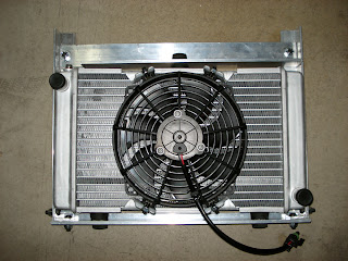
Essentially what I built is a frame made from various angle aluminum stock. The radiator doesn't have any screws or brackets that you can use to mount it to anything. All it has is three pegs meant to hold rubber bushings that would then be pushed into some mounting bracket. Try as I might, I could not find any bushings that would fit the posts. What I did find where rubber stoppers at the local hardware store. I bought three of them and drilled a hole through each. Then I constructed the frame, drilling holes to accept the "bushings" I made and then fastened the whole thing together. It turned out pretty well. The radiator is suspended in that frame via those bushings which provide a little shock absorption for the assembly. It will be suspended from the front battery rack by those two tabs you see sticking out of the top of the rack.
Once that was complete, I put the assembly in place and just clamped it so that I could start figuring out how to position the compressor. I was very worried that I'd have little to know extra room, but as it turns out, I have loads of space. I think there may be as much as a full inch in either direction for me to play with. That may not sound like much, but trust me, that is huge. I've had a difficult time fitting very nearly every component since I started the build, running short by 1/16th of an inch here or there was way to common. Very frustrating.
The A/C compressor will rest in a tray I've made, that will then be suspended from the front battery rack as well. Here is a shot of the tray I made today:

Notice the three large holes in the middle. They are for the rubber feet that hold the compressor, which cushion vibration while it's running. The tray is 1/8" aluminum plate surrounded by 1x1 inch aluminum angle stock. It is light yet remarkably stiff. The compressor weighs about 20 lbs, so it needs to be sturdy.
At this point, I'm very glad I made that rack out of steel. It will end up supporting 12 batteries, the power steering pump, the Zilla's radiator and the A/C compressor. Fortunately it's more than sturdy enough to support all that weight, as are the brackets it mounts to in the car.
My recent experience working with steel and aluminum for all the different support structures that I'm adding is not too dissimilar than my past experience. I've found that building an EV is an endeavor that requires a great deal of care and attention to detail. You decide how and where you're going to mount something, and measure the space. You measure even more carefully, and even build cardboard models. Then you begin cutting the metal you need. Once everything is cut, you start drilling and bolting and/or welding it into it's final shape. You then go back to fit it in the car, and discover that it won't work for some completely unexpected reason. So you scrap the whole thing and start over. Maybe it's just me, but this seems to be an ongoing theme.
Next I get to build the structure that this tray will be suspended from.
On a final note, I did finish installing the new Link-Pro meter in the car. It fit perfectly, replacing the Link-10 effortlessly. I still need to find a new place for that shunt, but I'm not too worried about that.
First things first. In order to mount the A/C compressor, I need to know how much room I have to work with. It's going to fit right behind the condenser for the A/C system and the new radiator I'm installing for the Zilla. But before I could measure how much space I needed to build the frame that will hold radiator and then mount it in place. Here's a shot of the radiator in it's frame:

Essentially what I built is a frame made from various angle aluminum stock. The radiator doesn't have any screws or brackets that you can use to mount it to anything. All it has is three pegs meant to hold rubber bushings that would then be pushed into some mounting bracket. Try as I might, I could not find any bushings that would fit the posts. What I did find where rubber stoppers at the local hardware store. I bought three of them and drilled a hole through each. Then I constructed the frame, drilling holes to accept the "bushings" I made and then fastened the whole thing together. It turned out pretty well. The radiator is suspended in that frame via those bushings which provide a little shock absorption for the assembly. It will be suspended from the front battery rack by those two tabs you see sticking out of the top of the rack.
Once that was complete, I put the assembly in place and just clamped it so that I could start figuring out how to position the compressor. I was very worried that I'd have little to know extra room, but as it turns out, I have loads of space. I think there may be as much as a full inch in either direction for me to play with. That may not sound like much, but trust me, that is huge. I've had a difficult time fitting very nearly every component since I started the build, running short by 1/16th of an inch here or there was way to common. Very frustrating.
The A/C compressor will rest in a tray I've made, that will then be suspended from the front battery rack as well. Here is a shot of the tray I made today:

Notice the three large holes in the middle. They are for the rubber feet that hold the compressor, which cushion vibration while it's running. The tray is 1/8" aluminum plate surrounded by 1x1 inch aluminum angle stock. It is light yet remarkably stiff. The compressor weighs about 20 lbs, so it needs to be sturdy.
At this point, I'm very glad I made that rack out of steel. It will end up supporting 12 batteries, the power steering pump, the Zilla's radiator and the A/C compressor. Fortunately it's more than sturdy enough to support all that weight, as are the brackets it mounts to in the car.
My recent experience working with steel and aluminum for all the different support structures that I'm adding is not too dissimilar than my past experience. I've found that building an EV is an endeavor that requires a great deal of care and attention to detail. You decide how and where you're going to mount something, and measure the space. You measure even more carefully, and even build cardboard models. Then you begin cutting the metal you need. Once everything is cut, you start drilling and bolting and/or welding it into it's final shape. You then go back to fit it in the car, and discover that it won't work for some completely unexpected reason. So you scrap the whole thing and start over. Maybe it's just me, but this seems to be an ongoing theme.
Next I get to build the structure that this tray will be suspended from.
On a final note, I did finish installing the new Link-Pro meter in the car. It fit perfectly, replacing the Link-10 effortlessly. I still need to find a new place for that shunt, but I'm not too worried about that.
Thursday, July 14, 2011
Now That's a Shunt!
There hasn't been a lot to report over the past few weeks. I've been dealing with acquiring the hardware necessary for the Air Conditioning system.
You may recall I'd ordered a Masterflux compressor and controller off a user on eBay for a bargain $200. The unit was reported to be new but old stock. In addition it required a 48 Volt DC supply. I'd been looking for how I was going to supply the necessary current to the controller at the proper voltage. Well the good news is that I've solved that problem, sort of. It turns out the compressor was not new, old stock. It was in fact used and not in good condition. The compressor had been crammed into the box along with two poorly protected controllers. Both had sustained damage while in shipment. Why the shipped two controllers, I have no idea.
Ultimately, I didn't trust either controller to work properly, and simply because of the circumstances, perhaps due to guilt by association, I didn't trust the compressor either. Everything went back.
Instead I have on order a brand new system that is designed to work directly off of my 160 volt DC system with no modifications required. The upside is obvious; the downside is it was $1200 more than the other system. Still, I'd rather spend the money and have a system that works. I don't want to mess with it once it's up and running.
In the mean time, I've been working on the revised motor mount. I cut and formed some steel and started dry fitting everything. Sadly I ran into another road block on this front. The problem I face is of course one of space. I need to get adequate shock absorption material under the motor. without any, it simply lays on the front steering rack with about 1/2" gap between the motor and the sub-frame right behind the steering rack. I need to support the motor so it's at least 1/4" off the rack so that it doesn't hit it during any vibration. More space would be better. The problem is that if I push the motor up too far, I begin to ruin the alignment of the drive line.
So, I need to find a way to support the motor in the proper position, with the proper attitude, provide shock absorption and tie it to the frame securely. I could go back with the previous solution I had, but I'd really like to add more shock absorbing material. The short story is that the pretty solution I drew up in the previous post simply won't work. Back to the drawing board.
I also started working on a minor part of the A/C system, and that was how to turn it on and off. The Z3 has a neat little button in the console with a picture of a snow flake on it. When you depress the button, it glows orange and turns on the A/C. I tried it out to make sure that it still sends a 12volt signal to the line that previously went to the compressor to turn it on, and no luck. I don't know if the ECU needed other connections from the wiring harness that are no longer there, but there was no way I could get that to power up.
Instead, I took the switch out, and started reverse engineering it. That switch also has the button to turn on/off air recirculation within the cabin. It has 8 points of connection. In short order I figured out which blade had power to it when all the right conditions were met; the A/C button was depressed, and the HVAC system fan was on. I simply spliced a new wire into that line so that I can draw 12V off it to power a new relay. That relay will turn on power to a fuse box that will provide power to the Masterflux controller and the AC condenser fan and a cooling fan for the controller itself.
I'm also taking this opportunity to swap out the Xantrex Link-10 meter I've been using, for a Xantrex Link-Pro. OK, it's actually the e-Xpert Pro; same thing. Why the change? You can chalk this up to a rookie mistake. In the beginning, when I was ordering all the parts for the car, I simply didn't understand how all of the component's specs needed to match up. I ordered a Zilla capable of putting out 1000 amps, and the Link-10 capable of reading only 500 amps. As long as I left the Zilla set to a 500 amp output or lower, then the Link-10 meter could measure the current accurately. If I set the Zilla higher, it didn't hurt the meter, but it simply didn't read the current, which meant the usage it reflected in terms of the battery's state of charge would be wrong.
Part of the package is a much bigger shunt, one that can handle 1000 amps vs. the 500 amp shunt for the old meter. Check it out...
 It reminds me of Crocodile Dundee, "that's not a knife..." That thing is huge! Which raises a concern as to where I'm going to put it. I think I'll be able to fit it where the old one was. I hope. Fortunately, the meter is exactly the same size and the leads I need to power it and provide data to it are identical, so it's a straight swap as far as that goes. I did opt for one other thing when I bought the meter, and that is a temperature sensor that I'll be running to one of the batteries. I'm going to pick one somewhere in the middle of the pack, one that is likely to get the warmest. In this way I can keep an eye on the temperature of the pack during the summer heat.
One other thing I've done was to remove the gaps between the batteries I have in the box under the trunk. I'd put gaps between them so that I could force air between them if necessary. I had installed a thermal switch that would turn on and force air over the batteries if they reached 125 °F. It never came on. Plus with the temperature monitoring I will now have on the meter, it's not really necessary. But the biggest reason is that I intend to replace all the copper straps that connected the batteries with braided ones. In order to do so, I need the batteries pushed together.
So, I pushed all the batteries together and then carefully measured and cut some wood to push into the space created. Mind you, this isn't to compress the cells, but merely to keep them from moving around.
 You can see it there over on the left hand side. As I'd mentioned before, and as several people have discovered, the cells do not expand unless you over charge or over drain the, rendering clamping them together unnecessary.
You may recall I'd ordered a Masterflux compressor and controller off a user on eBay for a bargain $200. The unit was reported to be new but old stock. In addition it required a 48 Volt DC supply. I'd been looking for how I was going to supply the necessary current to the controller at the proper voltage. Well the good news is that I've solved that problem, sort of. It turns out the compressor was not new, old stock. It was in fact used and not in good condition. The compressor had been crammed into the box along with two poorly protected controllers. Both had sustained damage while in shipment. Why the shipped two controllers, I have no idea.
Ultimately, I didn't trust either controller to work properly, and simply because of the circumstances, perhaps due to guilt by association, I didn't trust the compressor either. Everything went back.
Instead I have on order a brand new system that is designed to work directly off of my 160 volt DC system with no modifications required. The upside is obvious; the downside is it was $1200 more than the other system. Still, I'd rather spend the money and have a system that works. I don't want to mess with it once it's up and running.
In the mean time, I've been working on the revised motor mount. I cut and formed some steel and started dry fitting everything. Sadly I ran into another road block on this front. The problem I face is of course one of space. I need to get adequate shock absorption material under the motor. without any, it simply lays on the front steering rack with about 1/2" gap between the motor and the sub-frame right behind the steering rack. I need to support the motor so it's at least 1/4" off the rack so that it doesn't hit it during any vibration. More space would be better. The problem is that if I push the motor up too far, I begin to ruin the alignment of the drive line.
So, I need to find a way to support the motor in the proper position, with the proper attitude, provide shock absorption and tie it to the frame securely. I could go back with the previous solution I had, but I'd really like to add more shock absorbing material. The short story is that the pretty solution I drew up in the previous post simply won't work. Back to the drawing board.
I also started working on a minor part of the A/C system, and that was how to turn it on and off. The Z3 has a neat little button in the console with a picture of a snow flake on it. When you depress the button, it glows orange and turns on the A/C. I tried it out to make sure that it still sends a 12volt signal to the line that previously went to the compressor to turn it on, and no luck. I don't know if the ECU needed other connections from the wiring harness that are no longer there, but there was no way I could get that to power up.
Instead, I took the switch out, and started reverse engineering it. That switch also has the button to turn on/off air recirculation within the cabin. It has 8 points of connection. In short order I figured out which blade had power to it when all the right conditions were met; the A/C button was depressed, and the HVAC system fan was on. I simply spliced a new wire into that line so that I can draw 12V off it to power a new relay. That relay will turn on power to a fuse box that will provide power to the Masterflux controller and the AC condenser fan and a cooling fan for the controller itself.
I'm also taking this opportunity to swap out the Xantrex Link-10 meter I've been using, for a Xantrex Link-Pro. OK, it's actually the e-Xpert Pro; same thing. Why the change? You can chalk this up to a rookie mistake. In the beginning, when I was ordering all the parts for the car, I simply didn't understand how all of the component's specs needed to match up. I ordered a Zilla capable of putting out 1000 amps, and the Link-10 capable of reading only 500 amps. As long as I left the Zilla set to a 500 amp output or lower, then the Link-10 meter could measure the current accurately. If I set the Zilla higher, it didn't hurt the meter, but it simply didn't read the current, which meant the usage it reflected in terms of the battery's state of charge would be wrong.
Part of the package is a much bigger shunt, one that can handle 1000 amps vs. the 500 amp shunt for the old meter. Check it out...

One other thing I've done was to remove the gaps between the batteries I have in the box under the trunk. I'd put gaps between them so that I could force air between them if necessary. I had installed a thermal switch that would turn on and force air over the batteries if they reached 125 °F. It never came on. Plus with the temperature monitoring I will now have on the meter, it's not really necessary. But the biggest reason is that I intend to replace all the copper straps that connected the batteries with braided ones. In order to do so, I need the batteries pushed together.
So, I pushed all the batteries together and then carefully measured and cut some wood to push into the space created. Mind you, this isn't to compress the cells, but merely to keep them from moving around.

Tuesday, April 26, 2011
Earth Day and Some Coming Changes
This last Tuesday, the Arizona Army/Air National Guard post celebrated Earth Day. They invited a number of people to exhibit everything from composting technologies to solar panels. The also contacted me and asked me if I'd bring the EV Z3 down to show at the event. I let the members of the Arizona Chapter of the Electric Vehicle Automobile Association know about it as well, hoping there might be more than just the Z3 on display.
But of course, the event was held Tuesday during most peoples work hours, so it ended up being me and Gene Cosmano with his late 70's VW truck. Gene has installed a 600 Watt solar array on top of the truck which managed to fully charge his batteries while we were sitting on the field. He's put over 200,000 miles on the vehicle since it was converted in 93. It seemed the Z3 drew a bit more attention than Gene's truck, probably because it's a bit sexier, but I have to tell you, that truck is great piece of work. I was kicking myself that I didn't bring a camera to snap some pictures.
Anyway, the day went well, with lots of people stopping by and asking lots of questions. People are always surprised to find that I use the car as my daily driver. There wasn't anyone telling me I was an idiot for ruining such a nice car, but I did hear one guy telling Gene that he should hook up some generators to his wheels so he could charge the car while he drove. Apparently the first law of thermodynamics is really only a suggestion to this chap.
On to the next topic: Changes.
For some time now, I've been planning on doing some changes and performing some upgrades to the car. Some of these are pretty extensive, so this week I'm pulling the car into the garage, putting it up on blocks and starting the work. I've put this off for some time now for a few reasons. One, the weather has been beautiful and it's been so enjoyable driving with the top down, I simply couldn't bring myself to put the car in the dry dock. But second, since it is my only means of transportation (unless I take my other car back from my teenage daughter, and no one want's that) I have no vehicle. Well, yesterday I solved the last problem by buying an older Toyota Rav4 that I can use for a few months before selling it on. The coming of summer in Arizona has taken care of the first reason; it's starting to get hot enough that driving without AC is no fun. Which brings me nicely to one of the primary objectives.
Air Conditioning! I simply can't go through another summer in Phoenix without it. I have the original compressor and a small 120 VDC treadmill motor that I'm going to try to use to power the compressor. The problem is space. There's space under the front battery pack, and I'm hoping I can fit everything in there. If not, I may be buying one of the Masterflux AC units. But at $1200 for the compressor and the controller, I'm really going to try hard to get the motor/compressor combo to fit. I also need to solve the problem with the Zilla controller over heating and going into thermal cut back. The tiny radiator I'm using to cool it is simply not up to the task, so I'll be putting a much larger one in it's place.
One of the other things I need to do is build a proper motor mount for the WarP11. As I've thought about it over time, I've realized what I'd devised and put into place really isn't adequate. But there's one problem with that. Before I had the engine pulled, I failed to get one critical measurement. Remember this for when you do a conversion. Measure the distance from the from the top of the transmission to some fixed point on the car so that you'll know exactly where it should be placed, how high to elevate it when you're constructing the motor mounts to hold up the motor. This may not be an issue on some cars, but it was on the Z3. I failed to do this, so I was left to work it out based on making sure the drive shaft fit flush to the transmission output flange. Not the best solution.
So what's a guy to do when he needs that measurement and there's no way to get it from his car? I kept an eye out on Craig's list, and when someone advertised a version of the car identical to mine, I called and asked if I could measure it. The kind person that answer that call was Frank Froncillo, owner of a company called Critical Cut here in Phoenix. My request must have sounded very strange to Frank, but he was a good sport and told me to come on down and get my measurement. He also showed my the machines at his business, which were some of the coolest CNC machines I've ever seen. They use a super thin wire charged with several thousand volts to cut through any metal stock you need with astounding precision. He handed me two pieces of metal about 2 inches thick that had been cut to fit together like a puzzle piece with absolutely no play between them. One of the coolest things I've ever seen. I found myself trying to think of how I could incorporate something he'd cut into the car. Maybe Frank could make a motor mount... Anyway, if you ever read this, thanks a bunch Frank!
In addition to those changes, I've also purchased the newest version of the Xantrex Link 10 battery monitor called the Link Pro. The Link 10 is a great instrument. It fits beautifully in the dash and measures every variable I need (though I rarely take it off the "amp hours consumed" setting). The problem is that it can only read up to a 500 amp pull on the batteries. I could buy a 1000 amp 50 mv shunt and simply multiply most of the readings by two, but that would be a pretty rinky-dink thing to do in such a nice car. The new meter will measure an honest 1000 amps and allow me to turn the controller up so I can enjoy it's full potential.
One of the things the new meter will allow me to monitor is the temperature of the batteries. Well, one battery. I'll just bolt it to a terminal on a battery in the center of the pack and I can watch them to make sure they don't get too hot in the summer. So with a solid AC system, a bigger radiator for the controller and at least some temperature monitoring on the batteries, I should be able to drive on most summer days with no problems at all. At least that's the plan.
I have a few more things planned for the down time, but I'll bring those up as I tackle them. Stay tuned, it should be fun, and hopefully we'll all learn a thing or two.
But of course, the event was held Tuesday during most peoples work hours, so it ended up being me and Gene Cosmano with his late 70's VW truck. Gene has installed a 600 Watt solar array on top of the truck which managed to fully charge his batteries while we were sitting on the field. He's put over 200,000 miles on the vehicle since it was converted in 93. It seemed the Z3 drew a bit more attention than Gene's truck, probably because it's a bit sexier, but I have to tell you, that truck is great piece of work. I was kicking myself that I didn't bring a camera to snap some pictures.
Anyway, the day went well, with lots of people stopping by and asking lots of questions. People are always surprised to find that I use the car as my daily driver. There wasn't anyone telling me I was an idiot for ruining such a nice car, but I did hear one guy telling Gene that he should hook up some generators to his wheels so he could charge the car while he drove. Apparently the first law of thermodynamics is really only a suggestion to this chap.
On to the next topic: Changes.
For some time now, I've been planning on doing some changes and performing some upgrades to the car. Some of these are pretty extensive, so this week I'm pulling the car into the garage, putting it up on blocks and starting the work. I've put this off for some time now for a few reasons. One, the weather has been beautiful and it's been so enjoyable driving with the top down, I simply couldn't bring myself to put the car in the dry dock. But second, since it is my only means of transportation (unless I take my other car back from my teenage daughter, and no one want's that) I have no vehicle. Well, yesterday I solved the last problem by buying an older Toyota Rav4 that I can use for a few months before selling it on. The coming of summer in Arizona has taken care of the first reason; it's starting to get hot enough that driving without AC is no fun. Which brings me nicely to one of the primary objectives.
Air Conditioning! I simply can't go through another summer in Phoenix without it. I have the original compressor and a small 120 VDC treadmill motor that I'm going to try to use to power the compressor. The problem is space. There's space under the front battery pack, and I'm hoping I can fit everything in there. If not, I may be buying one of the Masterflux AC units. But at $1200 for the compressor and the controller, I'm really going to try hard to get the motor/compressor combo to fit. I also need to solve the problem with the Zilla controller over heating and going into thermal cut back. The tiny radiator I'm using to cool it is simply not up to the task, so I'll be putting a much larger one in it's place.
One of the other things I need to do is build a proper motor mount for the WarP11. As I've thought about it over time, I've realized what I'd devised and put into place really isn't adequate. But there's one problem with that. Before I had the engine pulled, I failed to get one critical measurement. Remember this for when you do a conversion. Measure the distance from the from the top of the transmission to some fixed point on the car so that you'll know exactly where it should be placed, how high to elevate it when you're constructing the motor mounts to hold up the motor. This may not be an issue on some cars, but it was on the Z3. I failed to do this, so I was left to work it out based on making sure the drive shaft fit flush to the transmission output flange. Not the best solution.
So what's a guy to do when he needs that measurement and there's no way to get it from his car? I kept an eye out on Craig's list, and when someone advertised a version of the car identical to mine, I called and asked if I could measure it. The kind person that answer that call was Frank Froncillo, owner of a company called Critical Cut here in Phoenix. My request must have sounded very strange to Frank, but he was a good sport and told me to come on down and get my measurement. He also showed my the machines at his business, which were some of the coolest CNC machines I've ever seen. They use a super thin wire charged with several thousand volts to cut through any metal stock you need with astounding precision. He handed me two pieces of metal about 2 inches thick that had been cut to fit together like a puzzle piece with absolutely no play between them. One of the coolest things I've ever seen. I found myself trying to think of how I could incorporate something he'd cut into the car. Maybe Frank could make a motor mount... Anyway, if you ever read this, thanks a bunch Frank!
In addition to those changes, I've also purchased the newest version of the Xantrex Link 10 battery monitor called the Link Pro. The Link 10 is a great instrument. It fits beautifully in the dash and measures every variable I need (though I rarely take it off the "amp hours consumed" setting). The problem is that it can only read up to a 500 amp pull on the batteries. I could buy a 1000 amp 50 mv shunt and simply multiply most of the readings by two, but that would be a pretty rinky-dink thing to do in such a nice car. The new meter will measure an honest 1000 amps and allow me to turn the controller up so I can enjoy it's full potential.
One of the things the new meter will allow me to monitor is the temperature of the batteries. Well, one battery. I'll just bolt it to a terminal on a battery in the center of the pack and I can watch them to make sure they don't get too hot in the summer. So with a solid AC system, a bigger radiator for the controller and at least some temperature monitoring on the batteries, I should be able to drive on most summer days with no problems at all. At least that's the plan.
I have a few more things planned for the down time, but I'll bring those up as I tackle them. Stay tuned, it should be fun, and hopefully we'll all learn a thing or two.
Tuesday, August 10, 2010
Interesting Results
Over the weekend, I ran the final test (for now) on the high voltage system. I hooked up the last piece of equipment to be tested, the DC to DC converters, and let the car sit for 3 days. By the end of the three days, the Link-10 showed that 2.18 kW-hs had been drawn off the pack. For those of you keeping track, you'll recognize that number as being very close to what we've seen in the past. Indeed, previous tests have all come up showing 2.15 kW-hs over the same time period. I'd mentioned that I expected this test to be a bit different because the fans for the DC to DC converters run continuously due to the ambient air temperature. So, at first glance it looks like we're seeing that difference. The interesting thing is what happened when I charge the pack.
On prior tests, the meter showed that the pack had lost 2.15 kW-hs, only to find when I charged the pack it would only accept around 200 W-hs. When I've worked out the math each time, I found that the Link-10 was introducing a about a 700 W-h per day error. If you want to be precise, it's actually 650 W-hs, but I rounded up 700 because it's easier for me to remember and for a few other reasons that would simply put you to sleep if I enumerated them.
Anyway, this time proved to be a bit different. I plugged in the car, started up the charger and stood there waiting for the charger to indicate it was done. I figured it would take 5, 10 minutes max. Well, after waiting for 15 minutes, and watching over a 1 kW-h be pushed to the pack, I realized that this wasn't going the way I'd expected. By the time the charger finally kicked off, it had pushed a total of 1.53 kW-hs into the battery.
Even though the Link-10 showed nearly the same draw over the 3 day test as it did on every other test, there had actually been a real draw off the pack that amounted to 511 W-hs per day! I'll talk about what the real power draw means to me and the car in a moment, but for now lets talk about the meter. The only problem is that I'm not so sure I can put it into words.
Essentially what we see is the meter failing to register the draw off the pack. Arguably, and presumably, if you increased the draw up to that magic 700 W-h per day error that seems to be inherent in the meter, the meter's reading wouldn't change much. For now, we can only speculate that would be true. What would be interesting to see would be if you increased the real draw on the batteries up to 800 W-hs per day. Would the meter begin to register that and show the real number? It's interesting to speculate, but I have no idea for now.
So what does the 511 W-hs per day that the DC to DC converters draw mean to me and the car? First, I'd like to know how much of that we can attribute to the fans. I can't easily get to the fans to see what their labels say with regards to power draw, but they seem to be ordinary 80 mm 12 VDC computer fans. One that I have laying around here says it uses .075 amps at 12 VDC. If we use those numbers (which are close enough for now), keeping in mind we have two fans, that comes out to a total of 43 W-hs per day. That seems like a pretty small fraction of the 511 W-hs that is actually being consumed. I can only assume that the remaining 468 W-hs is being gobbled up by the DC to DC converters as some sort of offering to the gods of inefficiency in the form of heat.
I think what that means is that it really would be worth while to look at turning the DC to DC converters off when the car is off. You may remember that I looked into that a couple months ago, installing a couple relays to turn the converters off when the car was off, and I ended up welding the relays shut. I contacted Ryan Bohm at EV Source and told him my dilemma. He recommended an "inrush limiter" for each of the converters. I ordered them and have them here. They really should be installed in the unit itself. Only downside there is that I have to take the converters out of the car to do so. Another task to add to the list of things to do. Mean while, the car still runs great and remains fun to drive.
On prior tests, the meter showed that the pack had lost 2.15 kW-hs, only to find when I charged the pack it would only accept around 200 W-hs. When I've worked out the math each time, I found that the Link-10 was introducing a about a 700 W-h per day error. If you want to be precise, it's actually 650 W-hs, but I rounded up 700 because it's easier for me to remember and for a few other reasons that would simply put you to sleep if I enumerated them.
Anyway, this time proved to be a bit different. I plugged in the car, started up the charger and stood there waiting for the charger to indicate it was done. I figured it would take 5, 10 minutes max. Well, after waiting for 15 minutes, and watching over a 1 kW-h be pushed to the pack, I realized that this wasn't going the way I'd expected. By the time the charger finally kicked off, it had pushed a total of 1.53 kW-hs into the battery.
Even though the Link-10 showed nearly the same draw over the 3 day test as it did on every other test, there had actually been a real draw off the pack that amounted to 511 W-hs per day! I'll talk about what the real power draw means to me and the car in a moment, but for now lets talk about the meter. The only problem is that I'm not so sure I can put it into words.
Essentially what we see is the meter failing to register the draw off the pack. Arguably, and presumably, if you increased the draw up to that magic 700 W-h per day error that seems to be inherent in the meter, the meter's reading wouldn't change much. For now, we can only speculate that would be true. What would be interesting to see would be if you increased the real draw on the batteries up to 800 W-hs per day. Would the meter begin to register that and show the real number? It's interesting to speculate, but I have no idea for now.
So what does the 511 W-hs per day that the DC to DC converters draw mean to me and the car? First, I'd like to know how much of that we can attribute to the fans. I can't easily get to the fans to see what their labels say with regards to power draw, but they seem to be ordinary 80 mm 12 VDC computer fans. One that I have laying around here says it uses .075 amps at 12 VDC. If we use those numbers (which are close enough for now), keeping in mind we have two fans, that comes out to a total of 43 W-hs per day. That seems like a pretty small fraction of the 511 W-hs that is actually being consumed. I can only assume that the remaining 468 W-hs is being gobbled up by the DC to DC converters as some sort of offering to the gods of inefficiency in the form of heat.
I think what that means is that it really would be worth while to look at turning the DC to DC converters off when the car is off. You may remember that I looked into that a couple months ago, installing a couple relays to turn the converters off when the car was off, and I ended up welding the relays shut. I contacted Ryan Bohm at EV Source and told him my dilemma. He recommended an "inrush limiter" for each of the converters. I ordered them and have them here. They really should be installed in the unit itself. Only downside there is that I have to take the converters out of the car to do so. Another task to add to the list of things to do. Mean while, the car still runs great and remains fun to drive.
Friday, August 6, 2010
A Quick Recap and A Few New Objectives
We're back from vacation and feeling great. Northern Arizona is beautiful country.
For those of you following along, you know I've been trying to sort out some apparent drain on the high voltage battery pack when the car is off. To do so, I've decided to test each, individual component, adding them one at a time to the system to see if I could determine the culprit.
What I was seeing, before the motor problems, was that when the car was sitting in the garage, off (or anywhere else for that matter), the Link-10 meter would report that approximately 1 kWh per day was being drawn off the pack. Through careful testing, I've discovered that the Link-10 is responsible for about 700 W/hours of that. That leaves about 300 W/hours yet to find. I say "about" because I didn't track the drain that carefully. It's just my recollection that it was about 1 kWh.
Anyway I've tested all the components, except for one, and found each draws no measurable power from the pack. Even the Link-10. It reports 700 W/hours per day, but it doesn't really use anywhere close to that. The only thing left to check is the DC to DC converters. Well, until summer ends, and the thermostat in the converters is happier with the air temperature, any test is not going to duplicate what I saw back in February and March. But I guess that's not entirely bad.
I've decided I'll go ahead and run the test with the DC to DC converters hooked up and running, even though the cooling fans will be spinning constantly the whole time. I'll still get some data, and it could be useful. I'll keep you posted on that.
By-in-large though, I think I've got most of what I was looking for. I know that the apparent draw off the battery pack, when the car is off, is a phantom. It doesn't exist. I wish the inaccuracy weren't there, but it is.
Now, there are still a few things that I need to do to the car. Some more important than others. I thought I'd share them with you now.
For those of you following along, you know I've been trying to sort out some apparent drain on the high voltage battery pack when the car is off. To do so, I've decided to test each, individual component, adding them one at a time to the system to see if I could determine the culprit.
What I was seeing, before the motor problems, was that when the car was sitting in the garage, off (or anywhere else for that matter), the Link-10 meter would report that approximately 1 kWh per day was being drawn off the pack. Through careful testing, I've discovered that the Link-10 is responsible for about 700 W/hours of that. That leaves about 300 W/hours yet to find. I say "about" because I didn't track the drain that carefully. It's just my recollection that it was about 1 kWh.
Anyway I've tested all the components, except for one, and found each draws no measurable power from the pack. Even the Link-10. It reports 700 W/hours per day, but it doesn't really use anywhere close to that. The only thing left to check is the DC to DC converters. Well, until summer ends, and the thermostat in the converters is happier with the air temperature, any test is not going to duplicate what I saw back in February and March. But I guess that's not entirely bad.
I've decided I'll go ahead and run the test with the DC to DC converters hooked up and running, even though the cooling fans will be spinning constantly the whole time. I'll still get some data, and it could be useful. I'll keep you posted on that.
By-in-large though, I think I've got most of what I was looking for. I know that the apparent draw off the battery pack, when the car is off, is a phantom. It doesn't exist. I wish the inaccuracy weren't there, but it is.
Now, there are still a few things that I need to do to the car. Some more important than others. I thought I'd share them with you now.
- Get the front end ride height adjusted.
- Get the front end aligned to remove any toe-in.
- Replace the differential fluid with Red Line (I did the transmission during the main build).
- Add an expansion chamber for the Zilla's coolant. You read that right. I didn't put one in when I was building the car. I realize now that wasn't the smartest thing, so feel free to mock me.
- Fit and adjust the v-belt for the compressor.
- Remove the AC lines and have them redone.
- Install a rubber membrane to the underside of the hood (bonnet, for my European friends) to keep the battery terminals off the steel in case of an accident. Let's hope that turns out to be a complete waste of time.
Tuesday, July 27, 2010
Getting Closer
This weekend's test with the Zilla attached proved to be as uninteresting as I had anticipated. The Zilla supposedly only draws 30 milliamps. What I found supports that. After three days with the Link-10, heater, charger, and finally the Zilla attached, the meter reported that 2.15 kWh's had been drained from the batteries. No different than any of the previous tests.
That leaves only the DC to DC converters left to test. As I've reported before, the ambient temperature here in Phoenix is high enough that the cooling fans on the converters run non-stop. I don't see any point in testing how much that draws off the pack. I'm far more interested in what is drawing power off the pack when the car appears to be doing absolutely nothing. But from the looks of things, that won't be the case until September some time.
For now I know that at least 700 of the Watt hours per day that the meter reports having left the pack is fictitious. I can live with that for now. I still have some other issues to deal with, which are minor in nature, but some of you may find interesting. Right now, I'm in lovely Sedona, so those will have to wait for next week.
That leaves only the DC to DC converters left to test. As I've reported before, the ambient temperature here in Phoenix is high enough that the cooling fans on the converters run non-stop. I don't see any point in testing how much that draws off the pack. I'm far more interested in what is drawing power off the pack when the car appears to be doing absolutely nothing. But from the looks of things, that won't be the case until September some time.
For now I know that at least 700 of the Watt hours per day that the meter reports having left the pack is fictitious. I can live with that for now. I still have some other issues to deal with, which are minor in nature, but some of you may find interesting. Right now, I'm in lovely Sedona, so those will have to wait for next week.
Friday, July 23, 2010
Testing: Stranger Still
I've been trying to determine which component is responsible for leeching power from the high voltage system when the car is idle. So far I've found that the Link-10 meter will unfailingly show a 700 Watt/hour per day loss, which I've determined to be largely inaccurate. I've run the same test with the ceramic heater hooked to the system (mind you it was off, just like the rest of the car) and it added nothing to the reported draw off the pack.
I finished a three day test yesterday in which I'd added the Manzanita Micro charger into the mix. At the end of the three day test I looked at meter, and what I found didn't surprise me at all. The meter read that there had been 2.15 kWhs drawn from the pack. That lines up exactly with what I would have expected, and so I can infer that the charger didn't draw any additional energy from the batteries. Again, not to surprising, but I have to test everything if I'm going to be thorough.
What was surprising is what happened when I charged the pack. In the first two tests, I saw that 2.15 kWhs had been drawn off the pack (according to the Link-10). But when I charged it, the charger read the pack as fully charged within minutes and when it finally shut off, it had only added 200 Watt/hours to the pack. So really, there was only 65 Watt/hours per day that were actually consumed. The first two tests had nearly identical numbers. Well, when I charged the batteries this time, the charger said the battery pack reached it's target voltage while I was turning the dial up to increase the current. When it finally kicked off, it had replaced a mere 60 Watt/hours. So, in this test, with only the Link-10, ceramic heater, and charger hooked to the high voltage system, their combined draw was 20 Watt/hours per day.
How could there be such a discrepancy? And how could the three components combined draw less energy than two of them? I think the answer is they didn't really. In spite of the fact that I'm trying to run these tests in the most controlled manner possible, I'm limited by the quality of the equipment. After all, it's not high dollar lab equipment, they're EV components. There is some inaccuracies inherent in each, i.e. the consistent 700 Watt/hour per day error in the Link-10. In this situation, I think we've exposed another inaccuracy in a different component, the charger.
The Manzanita Micro charger is fantastic as a bulk battery charger, and I think it does a terrific job. It is not a high dollar piece of bench lab testing equipment. It uses a potentiometer adjustment, made by the user, to determine the cutoff voltage for charging. I've set it such that the charger starts it's ramp down when the battery pack gets to ~165 VDC. It then ramps up to ~168 VDC before the timer runs out and it turns off completely. Now, the reason I use a "~ " is because it is it's all relatively approximate. Sometimes the timer comes on at 165 VDC, sometimes it comes on at 165.5 VDC. In addition, you may remember I'd said the algorithm it uses for how to ramp the current down is a complete and total mystery. So sometimes it will dump an additional 150 Watt/hours into the pack after the timer starts and sometimes (apparently) as little as 20 Watt/hours.
I guess the short of it is that using the charger as an instrument for doing the fine measurements I'd like to employ on this test is silly. At best I think I can only hope to get an idea of what's drawing current off the pack when the car is off. I've already discovered that the meter is responsible for most of what I've seen simply due to the error inherent within the meter. Am I going to find where that remaining 300 Watt/hours per day are going? I'm not sure, but I'm going to keep trying, and my feeling is that I'll find the DC to DC converters are drawing some of that current.
In any case, the next component to check is the Zilla controller. How much does it draw? Well it's supposed to be just a few milliamps. Over a 24 hour period, I'd be surprised if that registers on the meter. But I intend to test it anyway. That test began 30 minutes ago.
Stay tuned for the increasingly irrelevant conclusion!
I finished a three day test yesterday in which I'd added the Manzanita Micro charger into the mix. At the end of the three day test I looked at meter, and what I found didn't surprise me at all. The meter read that there had been 2.15 kWhs drawn from the pack. That lines up exactly with what I would have expected, and so I can infer that the charger didn't draw any additional energy from the batteries. Again, not to surprising, but I have to test everything if I'm going to be thorough.
What was surprising is what happened when I charged the pack. In the first two tests, I saw that 2.15 kWhs had been drawn off the pack (according to the Link-10). But when I charged it, the charger read the pack as fully charged within minutes and when it finally shut off, it had only added 200 Watt/hours to the pack. So really, there was only 65 Watt/hours per day that were actually consumed. The first two tests had nearly identical numbers. Well, when I charged the batteries this time, the charger said the battery pack reached it's target voltage while I was turning the dial up to increase the current. When it finally kicked off, it had replaced a mere 60 Watt/hours. So, in this test, with only the Link-10, ceramic heater, and charger hooked to the high voltage system, their combined draw was 20 Watt/hours per day.
How could there be such a discrepancy? And how could the three components combined draw less energy than two of them? I think the answer is they didn't really. In spite of the fact that I'm trying to run these tests in the most controlled manner possible, I'm limited by the quality of the equipment. After all, it's not high dollar lab equipment, they're EV components. There is some inaccuracies inherent in each, i.e. the consistent 700 Watt/hour per day error in the Link-10. In this situation, I think we've exposed another inaccuracy in a different component, the charger.
The Manzanita Micro charger is fantastic as a bulk battery charger, and I think it does a terrific job. It is not a high dollar piece of bench lab testing equipment. It uses a potentiometer adjustment, made by the user, to determine the cutoff voltage for charging. I've set it such that the charger starts it's ramp down when the battery pack gets to ~165 VDC. It then ramps up to ~168 VDC before the timer runs out and it turns off completely. Now, the reason I use a "~ " is because it is it's all relatively approximate. Sometimes the timer comes on at 165 VDC, sometimes it comes on at 165.5 VDC. In addition, you may remember I'd said the algorithm it uses for how to ramp the current down is a complete and total mystery. So sometimes it will dump an additional 150 Watt/hours into the pack after the timer starts and sometimes (apparently) as little as 20 Watt/hours.
I guess the short of it is that using the charger as an instrument for doing the fine measurements I'd like to employ on this test is silly. At best I think I can only hope to get an idea of what's drawing current off the pack when the car is off. I've already discovered that the meter is responsible for most of what I've seen simply due to the error inherent within the meter. Am I going to find where that remaining 300 Watt/hours per day are going? I'm not sure, but I'm going to keep trying, and my feeling is that I'll find the DC to DC converters are drawing some of that current.
In any case, the next component to check is the Zilla controller. How much does it draw? Well it's supposed to be just a few milliamps. Over a 24 hour period, I'd be surprised if that registers on the meter. But I intend to test it anyway. That test began 30 minutes ago.
Stay tuned for the increasingly irrelevant conclusion!
Monday, July 19, 2010
Testing Continued
Before I talk about the results of the most recent tests, I thought everyone might enjoy seeing one of the shots I took of the car, which I sent off for the book the EV Z3 is going to be in. Behold:

Considering the day was a bit cloudy and I don't own any lighting equipment other than a camera mounted flash, which I didn't use, I thought this turned out pretty good. Say what you want about the conversion, but it is a pretty car.
Anyway, back to the test results. So, over the weekend, I left the car idle, in the garage with only the following items attached to the high voltage side: the Link-10 meter, and the ceramic heater. As I mentioned in the last post, there is really no way for the heater to draw any current, but I swore I'd do more thorough tests, and that's what I intend to do. In fact, I decided against the idea of cutting that test short because I didn't expect the addition of the ceramic heater to amount to any difference. After all, if you allow your expectations to influence the method of your testing, your expectations influence and then determine the results of your test.
What did I find, you ask? Pretty much what I expected. The addition of the heater didn't change results at all. Over the time frame, the meter showed that 2.15 kWhs had been consumed. That is bang on what it said when I had only the meter attached. But if you remember back to that test, when I charged the batteries, they only accepted 200 Watt/hours. And after all, that's really what I need to know; how much energy was actually drawn out of the pack. This time was no different. About 3 minutes after I turned on the charger, the battery pack reached it's peak charging voltage and the charger began to ramp down.
By the time it had finished, 220 Watt/hours had been pushed back into the pack. I'm not concerned with that extra 20 Watt/hours that showed up in this test versus the first test. If I did the same test 10 times I'd expect 10 slightly different results because the charger introduces some randomness to the equation. The algorithm it uses to determine how many amps to push out while it ramps back down to zero during the cool down phase is anything but predictable. A 10% difference at this level is not a big deal. Considering the 2.15 kWhs the meter originally stated had been drawn off the pack, that 20 Watt/hours is only about 1%.
On the surface it would appear that I didn't learn anything. But really I did learn that the ceramic heater is definitely not drawing any current when it's off. It's true I expected that, but I also learned that the Link-10 showed the same error in metering 2 tests in a row.
In order to charge the battery pack I had to hook up the charger. That means that right now the Link-10, the ceramic heater and the charger are the only things hooked to the high voltage side. That sounds like a perfect recipe for the next test, which commenced 30 minutes ago.

Considering the day was a bit cloudy and I don't own any lighting equipment other than a camera mounted flash, which I didn't use, I thought this turned out pretty good. Say what you want about the conversion, but it is a pretty car.
Anyway, back to the test results. So, over the weekend, I left the car idle, in the garage with only the following items attached to the high voltage side: the Link-10 meter, and the ceramic heater. As I mentioned in the last post, there is really no way for the heater to draw any current, but I swore I'd do more thorough tests, and that's what I intend to do. In fact, I decided against the idea of cutting that test short because I didn't expect the addition of the ceramic heater to amount to any difference. After all, if you allow your expectations to influence the method of your testing, your expectations influence and then determine the results of your test.
What did I find, you ask? Pretty much what I expected. The addition of the heater didn't change results at all. Over the time frame, the meter showed that 2.15 kWhs had been consumed. That is bang on what it said when I had only the meter attached. But if you remember back to that test, when I charged the batteries, they only accepted 200 Watt/hours. And after all, that's really what I need to know; how much energy was actually drawn out of the pack. This time was no different. About 3 minutes after I turned on the charger, the battery pack reached it's peak charging voltage and the charger began to ramp down.
By the time it had finished, 220 Watt/hours had been pushed back into the pack. I'm not concerned with that extra 20 Watt/hours that showed up in this test versus the first test. If I did the same test 10 times I'd expect 10 slightly different results because the charger introduces some randomness to the equation. The algorithm it uses to determine how many amps to push out while it ramps back down to zero during the cool down phase is anything but predictable. A 10% difference at this level is not a big deal. Considering the 2.15 kWhs the meter originally stated had been drawn off the pack, that 20 Watt/hours is only about 1%.
On the surface it would appear that I didn't learn anything. But really I did learn that the ceramic heater is definitely not drawing any current when it's off. It's true I expected that, but I also learned that the Link-10 showed the same error in metering 2 tests in a row.
In order to charge the battery pack I had to hook up the charger. That means that right now the Link-10, the ceramic heater and the charger are the only things hooked to the high voltage side. That sounds like a perfect recipe for the next test, which commenced 30 minutes ago.
Subscribe to:
Posts (Atom)