Monday, October 15, 2012

EVCCON 2012, Charging, and a Watchdog

There's no denying it, this is a long over due update.  Since I last wrote about the charger blowing up, there have been a few events worth noting, and a change in the charging system worth mentioning.  Let's get to it.


EVCCON 2012


You may remember that my father and I took the Z3 out to Missouri last year for the inaugural EVCCON.  It was a fantastic event and before it even ended, I decided that Dad and I would return to EVCCON 2012.  There was a big difference this year in that we didn't take the car along with us.  Having the car out there last year was terrific, but trailer-ing it out there was stressful, expensive, and it took three days each way.  So this year the car waited back in the garage while we went to Missouri.

There has been plenty written of the convention on some very well written blogs, particularly on Mike Brown's blog about his Porsche 914 conversion, ( day 1, day 2 and day 3), and of course on EVTV.  What I was most taken back by was the quality of the builds this year.  I've been told by a number of people that they think I did a great job on the Z3.  Compared to most conversions I've seen, it is great.  Virtually all of the people that brought cars to this year's convention attended last year's and had a chance to see all of the cars that were brought at that time.  There were a handful of car's at last years convention that made the Z3 look like a kindergarten project.  It was evident by everyone that saw them, that they were clearly a different animal.  In fact, it's clear that the community has decided those cars are the new standard.  If you were going to convert a car, they were the benchmark that you need to aim for.  A challenge that all took seriously.

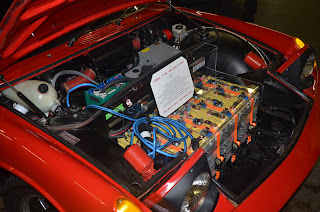
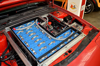
The quality of the cars this year was simply outstanding.  Everyone had all the components laid out and organized better than you'd expect an OEM to do.  All of the wiring was routed perfectly and protected in looms.  The connectors all neat and orderly, everything labeled.  Looking in to these cars was like looking in jewelry boxes.  Just astounding.  Here's a sampling of a few.  I wish I'd grabbed more photos.


Fred Behning and his MGTD


Jeff Greeson's 914.  Take away that blue cord and it's looks like a show piece.

John Allen's Celica.  A beautiful job in every respect.

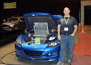
Kevin Heath and his RX8.  He has every reason to be proud of this build.

Jason Horack's Daytona.  Well laid out, neat and tidy.
Dale Friedhoff's Ranger.  It won best wiring/layout award.
It's inevitable that a fair number of people are going to look at any conversion.  The better they look, the more professional they appear, the more likely people are to take them seriously and not view them as a science project, or worse a rolling death trap that is bound to electrocute someone.  I personally think that producing fine cars like this pushes the cause of EVs forward a bit faster.

If I'm not mistaken, last year Dad and I were the only father/son team at the convention.  Well apparently that inspired a few others.  Several decided they wanted to share the experience with their fathers as well.  I was thrilled to see that list grow to 5 teams.  We took a moment to pose in front of Jack Rickard's original Speedster, along with Jack.
Left to Right, Me, my dad Bill, John Allen and his father, Nabil Hanke , John Hanke, Jack Rickard, Fred Behning and his dad Fred,  Brandon Hollinger and his father on the end.  

After a public car show in the park, the EVs went on parade through town and back to a local hotel were many of the attendees were staying.  They rounded up all the EVs that were in the parade for a photo op.

I think there are 33 cars in the photo, and I know of 5 others that didn't make it.  So that brings the total to 38 EVs at the convention by my count.  Not a bad turnout.  If you have the means to attend, I encourage you not to miss EVCCON 2013.  They are only going to get better from here on out.

Charger News

You may remember from my last post that my charger up and exploded on me.  It went back to Manzanita and they repaired it in a couple days and had it back to me right quick.  I think the charger was out of the car for less than a week.  All seemed well until a week after the install I noticed the charger behaving very erratically.  Though I'd dialed in 20 amps of current, I saw the meter bounce all around from 18 to 2 then 10 then 3 then 5 amps.  It was clear that it wasn't healthy. 

I contacted Manzanita again and explained what it was doing.  They asked me to take notes for a while to see if we could see a pattern to help them determine a cause.  If there was a pattern somewhere buried in the data I gave them, it escaped me.  After a couple weeks, we decided they needed it back to fix it.  I took it out and mailed it the day before Dad and I left for EVCCON.  

As it happens, Rich Rudman owner Manzanita Micro was one of the featured speakers at EVCCON, so I got to talk to him about the charger.  I offered to let him pick my brain about it's behavior hoping that he might have some insight into why it was doing what it was doing.  Instead it turned into a very short conversation.  Rich asked me if it was behaving erratically, and listed off a few of the key characteristics of the behavior.  I said "Yes! Exactly!"  He said "Yeah... we don't know what's causing that."  Apparently they've seen this a few times.  They suspect a specific chip on the power board is causing it.  When they come across this, they replace a few key components and that resolves the problem.

I got it back last Wednesday, they had it for about 2 weeks, and so far, I'd say they nailed it.  It has been rock solid reliable.  Boy, do I like that.  They really are a first rate shop.  

A Watchdog Circuit

It's happened twice now, which isn't a lot, but enough to make me a bit nervous.  The charger which usually cuts off when the pack reaches 164.5 volts has error-ed during the constant voltage portion of the charge cycle.  Instead of cutting off the charge in 10 minutes I set it for, it was well past 15 minutes, and I turned it off manually because the battery was going too high.  I was present on both occasions to catch it and prevent it from over charging the batteries.  But that begs the question, how many times did I not catch it because I wasn't there to watch? 

The truth is, the charger is pretty reliable, but it uses electronic components to process that logic and is subject to the same faults any electronic component is.  How many times does you computer do something unexpected?  The world is an imperfect place.  To that end, I've always thought that it would be worth while to have a separate circuit watching the charge cycle, one that had the ability to cut off the charge if things got out of hand.  Fortunately a couple simple components allow anyone with a Manzanita Micro charger to do just that.  I believe that other chargers have this capability as well, but I don't own any of them, so I can't say.

The Manzanita chargers were built incorporating what Manzanita calls the REG Bus.  I hear it does many things when coupled with other hardware that they sell.  But the truth is, I only need to use one of those functions, and that's the one that allows me to stop the charger.  

Pin 1 on the REG Bus supplies 5 volts DC.  Pin 2 has no voltage on it; however, if pin 2 sees 5 volts, the charger interprets this as an over charge condition and shuts the charging cycle off.  The charger remains on, with the fans cooling it, but the charging cycle terminates.  The bad side is, if you remove that 5 volts from pin 2, the charger immediately starts charging again.  So the trick is to get pin 1 and 2 shorted under the right conditions and leave them connected until the over charge condition goes away.  Enter the JLD 5740 volt meter.  At $37.50, it's a bargain.

The 5740 will measure anything from 0 - 500 Volts, DC or AC should you need it.  It has 2 relays that you can set independently.  You can set a relay to latch closed at one voltage, and open at a different voltage.  In this way, you can build in any logic for on/off you want.  Here's how I set mine up.

When I turn the meter on, the relay is open.  As the charge cycle runs, the voltage rises to the expected 164.5 volts.  If for some reason, the charger misses it's target, the meter is set to close the relay at 165.2 volts.  When the relay closes, the wire from pin 1 is shorted to the wire from pin 2 and the charger stops dead.  That voltage is low enough that no cell in the system will exceed 3.6 volts.  That relay then is latched closed until the voltage should drop below 158 volts.  Since the resting voltage of the system, after a charge is 160, then the meter will never (without intervention) open that relay, and the charger will never restart.  

When I built the car, I positioned a small switch under the charging door.  When that door is open the switch sends 12 volts to the charger, and it's presumed that I'm charging and the car is plugged in.  I run that 12 volt signal to the Zilla, which sees it and disables the car from moving.  I've simply spliced into that line and use that signal to power a separate relay, that then powers the meter.  I've incorporated the whole thing in a project box.  
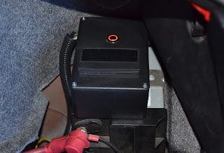
Notice the neat glowing switch on top of the box.

The switch is depressed and the meter is on.
I've run the power from the switch in the charging port to a second switch in the project box.  If I want to use the meter to watch the charger, I simply press that button and the meter comes on.  When I press the switch again, or if I close the charging port door, the meter is turned off.  I don't need for it to be on when I'm not charging, so there's no reason to have that parasitic load running.  

The only thing I haven't mentioned is that the 12V from the car that powers the meter first runs through a small 3 Watt DC to DC converter that isolates the high voltage on the meter from the car's 12V system.  We don't want the high voltage system leaking back to the chassis.  Pretty slick, and the whole thing cost less than $50 and it works great.  

Saturday, September 1, 2012

Heat: Not So Good for Chargers Either

A couple weeks ago, on a Monday morning, we were in off peak hours and I figured it would be a good time to top off the batteries before I ran the day's errands.  You may remember that I recently destroyed my eXpert Pro meter by re-applying the pack voltage to it and not removing 12V power first.  By the way, DON'T DO THAT!  Any way, I'd received a new one, but I hadn't yet installed it.  Without it, I have no idea how much current I'm pushing to the batteries, so I need to keep an eye on them to be sure I'm not over charging them.  The fact is you learn things when you watch what the batteries during charging.  Over time, I've learned quite a bit, and by watching them closely I can pretty much tell what's going on and predict when the charger will terminate.

At any rate, I know which cell will start to rise above 3.45V first, so I put a meter on it and started the charger.  For me, 3.45V is the top of the charge.  There simply isn't enough energy put into the cells above that point to justify the potential risk and damage to the cells by getting them to the manufacturer's 3.6V.  Ten minutes later, I walked out to see the voltage on the cell had climbed from it's initial reading of 3.26V  up to 3.380V.  I know by experience that means I'm about 35 minutes away from 3.45V when the charger should terminate it's charging sequence.  So you can imagine my surprise when I walked out 25 minutes later and found the battery at 3.364V, and the charger still running.  The voltage had dropped, yet the charger was still running.  I stood there for a moment, completely confused, it just didn't compute in my head.  Kind of like walking into your favorite BBQ place and seeing that it's full of vegans.  Not that there's anything wrong with it, but it just doesn't make sense.

Figuring that the charger must have just gotten confused (after all it does have a simple logic board in it), I figured I'd just reboot it.  I turned it off, waited 4 or 5 seconds and turned it back on.  The moment I turned it on, there was a succession of 3 pops, with the last one being quite loud and producing a bright orange flash and rush of hot gas shooting out the charger's vent port.  This was followed by me yelling "Oh shoot!", or something similar but perhaps more colorful.  I turned the charger back on... nothing.  Wasn't too surprised by that.  I checked the breaker on the house and had not tripped, so whatever failed in the charger failed in such a way that it simply consumed all the power coming into it and blew up, rather than shorting.  Or at least that's my take on it.

In either case, there was no doubt that I was going to need to remove the charger and send it back to Manzanita Micro for repair.  This was the second time I've had to do this.  The first was entirely self inflicted when I mistakenly shorted one of the batteries to the chassis with my multi-meter probe, while the car was charging.  That blew up the AC rectifier and melted the end of my probe.  I had no idea what happened here, but I boxed it up, got an RMA number and away it went to Washington.

It arrived in their shop on Friday and they sent me a note Monday afternoon that it was repaired, tested and ready for shipment.  Remarkably fast turn-around.  I called and spoke with Clarice, their office manager, to ask if they knew what caused the failure.  Clarice has seen enough repairs that she can recognize the likely cause of the failure just by looking at the parts that were replaced.  In this circumstance, both IGBTs failed as well as a capacitor.  She said she'd honestly never seen anything like it, but she'd ask Rich when he got it.  Rich thinks that one of the IGBTs failed and when it did, it took the other with it.  He thinks heat may have been a contributing factor.  This is where things get interesting and where there may be a lesson that all of you can learn at my expense.

As regular readers of this blog are aware, I live in Phoenix Arizona, which is slightly north of, and roughly rock throwing distance from Hell.  It's not uncommon for the inside of my garage to be 105°F.  If my wife pulls her car in after getting home from work, as it ticks itself cool, all the heat that was happily stored in all of that steel, gradually works it's way into the garage raising the temperature well over 110°F.  It's lovely.

Here's the thing.  Two years ago the car lived through it's first summer as an EV.  A significant portion of that summer saw the car dis-assembled because I had sent the motor back to Netgain because the balancing putty had fallen off.  Plus I took the opportunity to redo the battery layout.  So when it was back on the road in late July and I was charging it on a regular basis, I would come out to find the charger's yellow light flashing at me.  I went back to read the manual to find out what that meant, and I couldn't find a reference to what that was all about anywhere.  I figured it was just an oddity with this charger.  What it really was, was the charger warning me it was over heating.  I blissfully ignored this warning for the remaining portion of the summer.

As it happens, the car was taken apart for a good portion of the following summer to again fix a balancing putty issue on the motor, and to add air conditioning to the car.  In fact, I didn't get it back on the road until the first week of September, just in time to tow it out to EVCCON 2011.  But even then I would see the flashing yellow when charging, but by then I'd figured out what it was so I would dial the current back until the light stopped flashing.

That's been my modus operandi this summer.  I'd turn the charger on and dial in between 21 and 22 amps.  I'd poke my head back into the garage in 20 minutes or so and if the charger was over heating, I'd turn it down.  About 90% of the time, it was over heating.  I'd turn it down to 16 amps or so.  In retrospect, I think this behavior, and the initial instances of ignoring the warning, damaged the charger over time.  Heat is the enemy of all circuitry and when the charger was overheating, it felt quite literally like a blow drier firing out of that little vent port.  So my advice to you is don't to this.  I realize that most of you don't live in such hot climates, but for the few that do, pay attention to your charger.  Heat kills.

At this point, I intend to charge at 16 amps or so during the hotter months to protect the charger.  It's remarkable how much cooler the unit runs at that current level.  The problem is the charger was configured at a higher current level.  That means if I charge at a lower current level, there's a risk that the charger will overshoot the voltage I've set and consequently over charge the batteries.  Re-tuning the charger for a lower level is possible, but such a huge pain in the butt that I don't want to do it for the 1 month it's necessary before cooler weather arrives.  But I would like to be able to charge at any level I like and not risk over charging the cells.  I do have a solution in the works which I will be implementing and writing about soon, so stay tuned for that.  In the mean time, I'm going to have to watch the end of the charging curve very carefully to protect the batteries.

Thursday, July 19, 2012

A Look at the Bottom

Juvenile jokes aside, at the end of the last post I alluded to the fact that I was interested in seeing how the batteries were doing since I bottom balanced them in February of 2011.  Quite a lot has happened with the car since then.  The batteries have been through 353 cycles.  They've put out 2209 kWhs of electricity and then had it stuffed back in.  I've driven a total of 6324 miles.  The car has been out of commission twice for motor problems, and off the road for a grand total of 7 months.  During those occasions, the battery pack was partially disassembled with half of the cells out and laying on the floor of my garage, while the other half remained connected together in the car.   That last point has concerned me a bit.  I've wondered all along if having them apart might have introduced some variable that may have caused cell drift.  I kind of doubt it, but I simply wasn't sure.  So, I set out to find out. 

Last Sunday I had a chance to drive down to the brand new Tesla store in Scottsdale and take a first hand look at the Model S.  I even passed someone that was out for a test drive in one of the demo cars.  I don't believe I've seen a bigger grin on someone's face while they were driving.  It was a great trip, but I'll write about that later.  At any rate, with a round trip to Scottsdale, and a couple errands thrown in, I'd used about 95 amp/hours out of the pack's 120 amp/hours available.  I decided to make a quick trip out to run the batteries down a bit more.  I figured I'd get up to 115 amp/hours or so and then run the rest down by running the heater in the car.

I set off for a quick 10 mile lap that would do it, when I had a second thought.  I remembered that the last time I'd charged the batteries, the charge had cut off a bit early with the top cell being about 3.40 volts.  That equates to the pack starting off about 7 to 10 amp/hours down, so I decided to cut my trip short.  Turns out that was a good thing.

As I was driving adjacent to my neighborhood heading for a specific entrance, I noticed the car was not really accelerating any more.  A half mile before that I'd accelerated to 40 mph with no problem but now, it was acting dead.  I turned into the neighborhood quickly and headed for home nursing the car the whole way.  I'd brought my multi-meter along but I was afraid if I stopped, I wouldn't get going, so I coasted (running a couple stop signs along the way) and turned the final corner to my house.  As I was heading up to the garage, I was hoping the door made it open in time because if I had to stop, there was no way I was going to get it up the hill of my driveway into my garage.   I made it in, but the car was dead.  It would barely move the 6 more inches I wanted to go.  I quickly jumped out and measured the cell I know to have the lowest capacity and it was at 2.043 volts.  I started measuring others and they were in the 2.5 to 2.7 volt neighborhood.  Well, that doesn't seem balanced to me!  I decided to let the batteries rest for an hour or so and come back to measure them.

By the way, when I pulled into the garage, I'd used 113 amp/hours (for those of you keeping score at home.)

Now, I'll elaborate on this more in a moment, but take note.  The lowest cell was 2.043 volts right after it had had a load on it, which is just above what CALB considers dead.  The car would barely move.  Yet no cell was below 2.0 volts and no cell was ruined.

I came back an hour later and measured the cells and found that the gaps, or differences I'd seen in the voltages had closed up dramatically.  The lowest cell that was 2.043 volts had bounced back and was now 2.684 volts; the highest cell was 2.937 volts.   I should let the numbers speak for themselves.


You can see that the cells were mostly between the 2.700 and 2.800 range, with a few just 1/100 off in either direction.  But there were 4 that were more than 5/100's of a volt off, with the spread from the lowest to the highest cell at 0.253 volts.  Three things come to mind looking at this data.  First, they aren't balanced.  Second, the amount by which the are out of balance is quite small.  At that end of the discharge curve, the difference between 2.684 volts and 2.937 volts is a fraction of an amp hour.  The third thing is that I think I simply wasn't patient enough when I performed the bottom balance.  You may have heard this elsewhere, or experienced it yourself if you've ever bottom balanced a pack of batteries, but it is an extremely boring, tedious, and lengthy endeavor.  Or to put it another way, it sucks big time.

On that first attempt at bottom balancing, it wasn't until after I was sick of the whole process and charged the batteries back up that I realized the proper thing to do would have been to let them rest for several hours to be sure they remained balanced.  I had them all within 1/200ths of a volt when I charged them, but I now know that if I'd waited, I would have seen them settle, and found they were likely a bit further off.  I think that inaccuracy is reflected in the variations in this data. 

In spite of my ineptness demonstrated here, I must have balanced them well enough to be, what I consider, successful.  The car would not have moved another 10 feet if I needed it to, yet no cell went below 2.00 volts let alone reversed itself and died a horrible death.  Something a top balanced pack simply can't do.

Now, I know what you're thinking.  "But Tim, you brought on this situation yourself.  This was completely and utterly self inflicted!  There was no need what-so-ever to discharge the pack this much.  I never intend to take my pack that low and expose them to this peril.  Consequently I'll never face the jagged, rocky bottom of the discharge curve, risking one or any cells in the process."   In part, you're right.   But consider this.  These cells, like any other, lose capacity over time.  How much and how fast is determined by how you treat them.  The problem is, the dangerous, jagged bottom of the curve sneaks up with every charge.  In other words, a pack that started out as a 120 amp/hour pack eventually becomes a 110 amp/hour pack, and then 100 amp/hour pack.  If you don't know where the bottom is, you risk hitting it and running a cell or 10 into reversal.  Since mine are bottom balanced, I "see" that imbalance at the top.  The charger cuts off at a preset voltage and the batteries will eventually reach that voltage regardless of how many amp hours they can actually hold.  The difference is, if I hit bottom the car stops moving and the batteries are fine.

So what's a fella to do at this point?  Best try to balance them again and do it properly.  This was monumentally difficult.  Not because the job is hard, and not because the batteries put up a fight or anything.  Rather because it's miserably hot and humid in AZ at the moment and spending 3 days in the garage balancing the batteries was not my idea of a good time.  One of those days was 18 hours long!  Suffice it to say, I got them all between 2.757 and 2.761, 4/1000ths of a volt, and that was with letting them rest for 4 hours at the end, before I put the charger on them.

One of the key pieces of information I wanted to get and was eager to share with you was the total number of amp/hours that went back into the pack.  That really is a measure of how the batteries have held up to the 545 cycles they've seen.  Sadly because of another, yet different stupid mistake, I'm not able to share that with you.  In may haste to get the pack balanced and the car back on the road, and my zeal to get it done right, I forgot something very important.  When ever you disconnect the main battery pack from an e-xpert pro meter, you MUST remove power from the meter.  I forgot to do this.  I opened the car and saw the following...


Notice the haze in the lower corners of the display?  The sharp eyed ones among you may also notice that the meter is not actually displaying any data.  I opened the door and immediately smelled the distinct aroma of a fried circuit board.  NOOOOOOOOOOO!   It gets better.  I took it out this morning, hoping to send it back to Evolve Electrics for repair, and this is what I discovered:


I'm no doctor, but that does not look good.  This meter was a few oxygen atoms away from catching fire.  I'm not sure if the deformation of the cylinder is clear in the photo, but it is not healthy looking.  Don't be like Tim.  Disconnect power from your meter before you work on the battery pack.  Incidentally, it fried the 1:10 prescaler as well.  *Sigh*

So, the end result of that is that I don't have a precise number to give you regarding how much power the batteries were able to accept when I finally charged them.   I can tell you that I turned the charger's dial to what I believe to be the position where it delivers 20 amps, and it took almost exactly 6 hours to charge.  That works out to 120 amp/hours, but it's really no better than a guess at this point. 


Monday, July 9, 2012

10,000 Electric Miles

I pulled into the garage last night and noted the amp/hours I'd used and the mileage on the odometer so that I could record them like I do every time I charge the car.  The mileage read 144,214 which is significant because that marks exactly 10,000 miles since the Z3 was reborn as an EV.  I figured that this would be a good time to go over some of the numbers I've been collecting that last 2 years, 4 months and see what I could glean, and then share them with you. 

530        Number of Charge Cycles

18.9       Mean average miles driven between each charge
34.9%    Mean average depth of discharge
36.0%    Median average depth of discharge (half the data points are above, half below 36.0)


WARNING: Wild numbers and speculation will now commence. 

CALB says that these batteries are good for 2000 cycles at an 80% Depth of Discharge (DOD), and 3000 at 70%.  But how long will they last if I'm averaging roughly 35% DOD?  Of course no one knows.  However, if you use the 50% increase we see going from 80% DOD to 70% DOD as a baseline, and extrapolate that out, we might be able to conclude that we could get 4500 cycles at 60% DOD.  If we keep going and then apply it to my average DOD of ~35%, we come up with something close to 12,500 cycles.  At 18.9 miles per cycle, that works out to 236,250 miles. 

Of course that's all theoretical, but it's likely not too far off from reality.  But let's be conservative and say I only get half that number of cycles out of the batteries, that's still 118,000 miles.  However, we need to keep in mind that the original 2000 and 3000 cycles that CALB states is a bit misleading.  It's not as if the batteries stop working when they get to 2000 cycles.  What they really mean is that after 2000 cycles to 80% DOD, the battery will only hold 80% of it's original capacity, so they will still push the car as far as I need to drive on a daily basis.

</Wild numbers and speculation>

As you can see this whole "cycle life" or "life expectancy" question for the batteries is highly fluid with the real numbers determined by a number of factors all at once which are, for practical purposes, impossible to determine or track.  One thing that is certain is that these batteries will out perform a lead acid pack by at least an order of magnitude.  Seeing as they only cost 4 times as much as a lead acid pack, I call that a good bargain.  And that's not even taking into account the numerous other benefits they offer, like the 60 mile range vs. a lead acid packs 20 miles (at best). 

$1,402    Amount saved not buying gas
3639       Total number of kWhs used to charge the car

That $1,402 figure is derived by taking into account the price of gas when I charged the car and subtracting the cost of the electricity used to charge the car.  I always charge the car at off peak hours, and I add an extra 10% to the amount of electricity consumed to take into account the inefficiencies of the charger as it converts the 240 Volts AC to 160 Volts DC. 

So how has the car performed?  How well has it used that energy?

376        Mean average Watt-hours consumed per mile
388        Mean avg Watt-hours/mile with the old solid brushes
319        Mean avg Watt-hours/mile with the new split brushes

You can see there's been a marked difference in efficiency since replacing the brushes.  The old average of 388 Watt-hours per mile was experienced over 442 charge cycles and 8,184 miles.  The average has dropped to 319, and that has been over 88 charge cycles and 1,816 miles.  I don't know how one could dispute the claim that these Helwig Carbon split Red Top brushes are better. 

That increase in efficiency has moved the car from a 50 mile range using the 388 Watt-hours per mile figure to 61 miles using 319 Watt-hours per mile.  Of course most of you know how much range can fluctuate with an EV depending on how and where you drive.  I've been on 40 mile trips with the car where I saw the energy consumption average drop to 266 Watt-hours per mile, which works out to 73 mile range.  Is that useful data?  I don't know, but it's interesting.

Expanding on that, I found 4 data points that fit together nicely.   These are individual trips with the miles driven, the total kWhs used and the Watt-hours used per mile.

50 miles      17.23 kWhs    345 Watt-hours/mile
51 miles      17.89 kWhs    351 Watt-hours/mile
51 miles      16.49 kWhs    323 Watt-hours/mile
51 miles      14.57 kWhs    286 Watt-hours/mile

Guess which trip occurred after the new brushes were installed in the motor.  By the way, those were all trips to the same destination and back.

The real question at this point is how are the batteries fairing?  For those not familiar with the car and reluctant to go back and read the multitude of tedious posts, I bottom balanced the pack back in February of 2011.  The only way to find out how the batteries are doing now is to draw the pack back down to the bottom and make note of the amp/hours taken out and the state of charge on each battery.  Hmm... sounds like another post.  Stay tuned.

Tuesday, June 5, 2012

On Power Steering and a "Normal" Feeling Drive

Anyone who's been reading this blog for a while, knows that I have a Toyota MR2 electric hydraulic pump running the power steering system.  Take the ICE engine out of a car, and chances are your power steering pump goes with it. 

There are a few ways of dealing with this problem.  One is to simply fore-go power steering.  But unless you replace the steering rack with one that's geared for non power steering, that makes turning at low speeds rather like arm wrestling with Lou Ferrigno.   The second is to build some apparatus for holding the old power steering pump onto the front of the electric motor, putting a pulley on the tail shaft of the motor and powering it off that.  Of course, if the motor isn't spinning, you have no power steering.  For me and I'm guessing many others, there simply wasn't enough room to incorporate something like that.  You'd be surprised how many times you run out of room and 1/16th of an inch more was all you needed to make something fit.

The third, and perhaps most popular remedy is to use an electric power steering pump.  There are a few OEM cars out their using such devices and the second generation Toyota MR2 was one of them.  They cost somewhere around $300 to $400, they don't take up much room and its relatively inexpensive to have the custom hoses made to add them to the system. 

On a normal car, they run all the time and you really wouldn't care because the alternator will just produce the energy it needs to work.  But in an EV, you want to try and reduce parasitic loads.  That pump can draw up to 85 amps in a hard lock!  So the idea of having it run all the time was troublesome to me.  To resolve that, I devised a system by where the pump stayed off when driving in a straight line, but would come on as soon as you turned the wheel a few degrees.  I also added an off-delay relay so that it would remain on for 10 seconds after I was going straight.  In this way, it wouldn't cycle on an off while I was going through a parking lot or some other place requiring a lot of turns. 

But it wasn't a perfect solution, and I grew to dislike it for two reasons.  One was that it proved to be dangerous.  As is bound to happen when driving, it became necessary for me to quickly dodge something in the street.  The amount of effort it takes to begin turning is massive.  So when the pump kicks in, you just can't react quick enough to release the pressure.  I ended up nearly steering right into the car next to me.  It left me with a case of the sweats as I pondered the fact that I'd nearly caused an accident and destroyed all my hard work.

The second reason was that when I would have other people drive the car (something I do as frequently as possible) they had a difficult time getting used to that sluggish, stiff steering wheel when heading into a corner.  I thought, "how can I convince people that EV's are fun to drive and just like any other car, only better, when they had to wrestle the steering wheel going into any turn?  This was not the message I want to convey. 

I thought I would simply put a latching switch into the system that would allow me to bypass the proximity switch on the steering column which would then turn the system on and leave it on until I pressed the switch again.  Seemed like the perfect plan and I even had a great place to locate the switch in the cabin.   So, before I took the car apart to work on the last motor problem, I ran a few tests to find out just how much power the pump drew when I was traveling in a straight line.  It turns out that it draws less than 2 amps from the high voltage pack.  That translates into something like 18 to 22 amps on the 12 volt system.  Not trivial, but not too bad.  The system is sized to accommodate it.

The point is, I could let the car sit idle running that pump and it would take over 60 hours for it to deplete the battery pack.  That means in a standard commute to work, which takes 20 minutes, the power steering pump uses an extra... let me think... about, Oh I don't care!!  It's seriously not enough for me to worry about AT ALL!  Since the car has been on the road, I've left that switch engaged the whole time.  My previous post detailed how I've experienced a boost in efficiency seemingly from the new brushes, so the change to the system of having this pump run all the time might have had an adverse impact on that, but it's not enough that I care. 

The car drives like a normal car now, in almost all respects.  I don't have to explain to people that drive it why the steering feels weird at first, and they don't have to experience the sharp jerk when the pump kicks on and they aren't expecting it.  This is definitely the way to go. 

By the way, I have turned it off a couple times.  Sitting, waiting for my daughter to finish her choir practice, I left the car on so I could listen to the radio and enjoy the air conditioning, but I turned the pump off.  Honestly, I'm not sure it was worth the effort of lifting my hand to press the switch. 

Monday, May 14, 2012

Efficiency I Can't Quite Explain

With the exception of the few months the Z3 has been off the road for repairs or upgrades, I've been driving the car for just over 26 months.  During that time, I've kept detailed records of every charge/discharge cycle of the batteries.  Every time I plug in, I note the mileage on the odometer, and the number of amp hours I've drawn out of the pack.  I then take that data and plug it into a spreadsheet that calculates a number of things for me, including how much money I've saved because I wasn't burning gas, how much the electricity I'm using is costing me, and most interestingly, how many Watt-hours per mile the car is using.

I've reported in the past the the car averages about 320 Watt-hours per mile on surface streets.  That's the number I've used to calculate the range of the car: 19,400 Wh / 320 Wh = 60.625.  This is why I've always stated the car has a 60 mile range.  And I've proved that out once, driving 62 miles on a charge once, in preparation for doing a bottom balance on the batteries.

Of course, once I go on the freeway traveling between 65 and 70 mph, that 320 Watt-hours per mile begins to look like a distant dream.  The aerodynamic drag on the car causes energy consumption to quickly rise to around 420 Watt-hours per mile at 65 miles an hour.  That meant that my round trip to work, a 23 mile journey, which includes 7 miles of surface streets and 16 miles of freeway, averaged between 370 and 380 Watt-hours per mile.  I've made this trip a few hundred times, I know the numbers.

It's no secret that I've had a few problems with the motor in the car.  The balancing putty has come off for a some inexplicable reason, twice.  Just recently it developed a short to the case that no amount of air blown through its guts could resolve.  George Hamstra at Netgain has been a champion through all of this and ultimately had a new motor sent to me.  In addition, we swapped out the brushes from the standard H-49 brushes used for high current applications like drag racing, to H-60 brushes which are better suited for street use.  A cool feature on Helwig H-60 brushes is the split, Red Top design, which helps to ensure better contact on the commutator.

At any rate, I got the new brushes seated in the motor properly, put the car back together and launched it back onto the streets about 3 weeks ago.  The car is my daily driver, so once I began driving it to work and other places, and recording the energy consumption, I was a bit surprised to notice it was more efficient.  At first I thought it was maybe just an anomaly, but it's clear something has caused the car to make much better use of the energy in the batteries.  My round trips to work are now averaging about 280 Watt-hours per mile.  Compare that to the older 370!  That's more than a 25% improvement in efficiency!  I made one trip where the average dropped to 266.

Today I took a bit of a longer trip out to Scottsdale.  A total of 38 miles, with 30 of those miles on the freeway, traveling around 70 mph.  The average consumption for the entire trip was 274 Watt-hours per mile.  In the past, I would have estimated this trip to be a 400+ Watt-hour per mile trip.  But that's not all!  During the entire trip, I had the AC system on (which draws about 9 amps) and of course, I've configured the power steering pump to run all the time now adding another 2 amp continuous draw.  BTW, the change to the power steering is interesting, but that's another post.  So there are more parasitic loads, yet, efficiency is up.

The one thing I haven't done yet is to see what average I would get if I traveled at 40 or 45 mph.   There's no reason to think the gain in efficiency that I'm seeing wouldn't appear there as well, but I simply don't have those numbers yet.

It seems like an obvious conclusion to draw that the increase in efficiency can be attributed to the new motor, or brushes, or a combination of them both.  But I really can't say that with certainty.  Perhaps I'd made some error when installing the drive line in the past which caused some binding or friction that I simply wasn't aware of.  I kind of doubt that, but who knows?  There's no question I've gotten better at disassembling the drive line of the car, but there really isn't much room for error here.  I have no reason to doubt the numbers the meter is giving me; after all, it's the same meeter with the same set up I was using before the motor swap.

What ever the cause, the car does seem to be more efficient.  At an average draw of 280 Watt-hours per mile, it's gone from a 60 mile range to nearly a 70 mile range.  I'll take it.

Update 5/20/2012:

I've continued to see the gains in efficiency I detailed above, but I've realized I've let myself fall victim to insidious creature that is over optimism.  I've always maintained that the Z3 had a 60 mile range.  That was based on the fact that it consumed about 320 - 330 Watt-hours per mile when driving at ~45 mph in normal traffic.  What I really hadn't done is take an average over multiple trips to get a more balanced number, a real world number you can take to the bank.  Well since I've seen this improvement in efficiency, I've gone back  to my spreadsheet to see if I could mine some more useful, accurate data from the numbers.  Here's how it works out...

Since the car was put on the road, up until the motor/brush replacement, it has averaged 376 Watt hours per mile.  That is the real world average.  Sure there were many trips that were better, but there were also many that were worse.  I can't get out of my neighborhood without consuming something like 480 Watt-hours per mile.  It's all about stopping and starting.  With no regenerative braking, stop signs and stop lights really affect your range.  The more of them per mile, the worse your range.  Well, there's 6 stop signs on one of the routes it takes to get from my house to the main streets, so you can imagine what that does to energy consumption.

The average after the motor/brush swap has dropped to 321 Watt-hours per mile.  Compare that to the old 376, and you note a 14.7% improvement.  That is huge!  Interestingly, and I've mentioned this above, virtually all of the trips I've made in the car since putting it back on the road have been on the freeway at 65 - 70 mph.  Meaning, that as more trips on surface streets are recorded I expect that 321 number to drop even further.

The bottom line is that I've been misrepresenting what the car's range really is by skewing the data toward the happier, more optimistic lower numbers.  Not intentionally or maliciously mind you.  The old average was 51.6, the average now seems to be 60.4.  A painful thing to admit, but there you have it.  Just as I could have easily squeezed 60 miles out of the car before, sticking to surface streets and avoiding stops, I expect I could squeeze 70 miles out of it now, doing the same. 

I've brought all this to Jack Rickard's attention at EVTV, and just like me, he was skeptical and ultimately amazed.  He's been doing some tests swapping out the original H49 brushes for the split, Red Top H60's and he's finding the same results.  I have a feeling this is going to be a hot topic in the EV community for a while.

Monday, April 23, 2012

What An Ordeal

The few of you who read this blog have probably wondered what's been going on with the Z3.  When I last left you, I'd received the new motor, had put the new split top, harder brushes in and was seating them by running the motor off of a 12V battery.  Well, quite a lot has happened, and frankly, it wasn't all good.  So sit back and enjoy the saga.

Once I installed the new brushes and turned the motor on, it made a hell of a racket for the first few hours.  I remember seeing a video John Allen had made when he was breaking in new brushes for his Warp 9, and I was struck by how loud it was, so I wasn't too surprised when mine made similar noises.  I ran the motor for 100 hours and at the end, it sounded as smooth as silk.  Job done!

I mounted the motor up to the transmission and tightened up all the bolts and called it a day, planning to reinstall the motor/transmission back into the car the next day.  During the night, I realized I'd done something kind of stupid.  The manual for the car states that you should put a little grease on the input shaft before you mate it up to the motor.  It already had a film of grease on it, but I thought more is better.  When thinking about it that evening, I realized that I had cleaned off a little grease I'd found on the flywheel.  It was in a pattern that looked like it had been thrown off the shaft.  It was at that point I realized more is not better, and I'd set myself up for a greasy, slip prone clutch.  So I took the tranny off the motor, cleaned the shaft of excess grease and mounted it back up.  It only took 45 minutes or so, so it wasn't that bad.  I'm telling this story so that if anyone out there reading this can learn a lesson from my stupidity, then I've served some purpose on this planet.

Moving on.  The motor/transmission assembly went in to the car later that day without a hitch, and thanks to my dad who came out to help me.  I mounted up the drive line and started the process of re-assembling the car.  It went quite smooth really.   I was making one of the last battery connections when I leaned my elbow on the chassis, and it felt like I got stabbed or cut.  I remember thinking that I didn't remember the bolt I leaned on being particularly sharp.  I touched it again and realized that I didn't get stabbed, I got shocked.  That's right my friends, the leak, which I was trying to get rid of, the one for which I'd been sent a replacement motor, was not gone.

Talk about a kick in the teeth.  I started testing and dis-assembling everything and came to the conclusion that, once again, the source of the leak was in the motor.  How could this be?!!!   I was absolutely gutted and just walked away from the car for what ended up being the whole weekend while I thought about what to do.

I decided what I had to do was figure out, definitively if it was the motor or something else.  I decided the best way to do that was to assemble all of the components completely, but leave the motor out of the assembly process.  In place of the motor, I simply ran a cable from the Motor + terminal on the controller to the Motor - terminal.  This was simply to replicate the existence of "something" in the system at that position in the circuit.  Once it was all back together (minus a few batteries) I found that there was no leak. I added the motor back in, the leak appeared.

I thought perhaps breaking the brushes in had created enough dust to cause the problem, so I decided to blow it out with compressed air.  While some dust did come out, I could still measure the HV pack voltage on the chassis.  Ghaaaa!!

It was time to contact George again.  I can't express to you how much I did not want to darken his inbox with bad news again.  George asked if I would send him and Tom Brunka of Helwig Carbon Brushes a picture of one of the brushes that I broke in.  He wanted a close up of the face and shot of the profile.  Puzzled, and unsure of how that would help, I obliged and sent off the photos.  Tom got back and said that the brushes looked like they were broken in perfectly, so that was good.  But then he apparently noticed something else, and that was the model number printed on the brush indicated it was for a 9" motor.

The pieces started falling into place for George at that point.  The commutator on a 9" motor has a smaller circumference than that of an 11" motor.  That means that the brushes for a 9" motor would be made with a smaller arc to the face.  Aside for that, they are identical in function, composition and structure.  But what that meant was that rather than the brush's surface resting with more or less complete contact on the commutator, it was riding on the very edges.  That explained why they were so loud when I first put them in.  Truthfully, at that time, I even wondered if I might have been sent brushes for a 9" motor, but it was just a passing thought.

So, through an innocent mistake, George had sent me the wrong brushes.  He mentioned that it really was no problem to use them now that they were seated so well, and I would have had to wait another 2 weeks to get 11" brushes anyway.  I was fine with keeping these.  Anyway, because the brushes weren't contoured correctly for the 11" motor, that meant that a bit more material had to wear off of them than would have normally happened.  Couple that with the fact that when running off a 12V battery, the motor doesn't spin fast enough to create enough airflow to vent the dust that does come off the brushes, and you have a recipe for developing and internal path to ground.

I went back and measured the resistance of the path from the motor terminal to the chassis and found that it was .880 mega Ohms.  Don't ask me why I didn't measure that after I blew the motor out the first time, but I didn't think to.  I saw that I could measure voltage on the chassis and felt that was enough of a problem that I didn't think to measure resistance.  But what I found was that after I had blown it out, it had made a difference.  .880 mega Ohms can only pass 0.13 milliamps at 160 volts.  I could touch the terminal of the battery and the chassis and felt nothing.

George added that once I got the motor back on the road and spun it up to 3000 RPM, it would blow the rest of that dust out.  he also mentioned that Warfield Electric consider a leak to chassis acceptable as long as it won't light up a light bulb.  Well, .13 milliamps isn't enough to light a light bulb, and it's also not enough to cause my charger to complain.

Today I got everything back together, tested the systems, and flipped the charger on with fingers crossed.  It came right on and dutifully charged the batteries back up to full.  All systems go!  I took the car down from the jack stands drove it out of the garage and put 20 miles on it this afternoon.  It seemed like everyday since the car has been out of commission, I came across either a Nissan Leaf, or a Chevy Volt, while out driving and I would just grumble in envy.  Today I saw Leaf  while I was driving the Z3, and I simply felt joy.

Thursday, March 22, 2012

Seating New Brushes

You're probably familiar with the problem I've been facing recently regarding the leak to chassis ground through the motor.  It's proven to be a very strange problem. I made a quick video to demonstrate what I'm seeing, take a look.


A leak at 635 Ohms and 160 volts equates to 252 milliamps.  The 436 Ohms I read the following day would produce a current leak of 367 milliamps.  I've seen the reading as high as 1180 Ohms, and as low as 350 Ohms.  This sort of leak is most often caused by the accumulation of dust in the motor.  I've blown enough air through the motor that if that were indeed the problem, it should have fixed it.  But as you all know it hasn't, so George Hamstra has decided he's seen me suffer enough at the hands of this motor, so he's sent me a new one.


 Since that picture was taken, I've pulled the clutch assembly, flywheel, adaptor plate and taper-lock hub assembly off the old motor with the help of my friend Dave from Tucson.  However, I haven't put it on the new motor yet.  In email exchanges with George, I mentioned that I would be sending back the $320 brushes he sent me (at his expense) to try to resolve the problem with the original motor.  But he replied saying instead that I should put them in the new motor.  He believed that the brushes in the new motor were likely brushes better suited for racing.  I peered in the motor and found they were the Helwig Redtop brushes, but when I compared them to the ones George had sent me I could see a marked difference.  They were a bit shorter, but much darker in color.

So at George's recommendation, I swapped them out.  But that means I need to seat, or bed in the new brushes before I put the motor in the car.  Essentially, you strap the motor down, and connect it to a 12v battery and let it spin for 100+ hours.  It sounds easy enough, but actually getting it done required some effort.

First I needed a 12 battery.  I don't have one laying around, so I went to the local Costco and bought the cheapest 12v deep cycle battery they had for about $80.  I was under the impression that the motor would draw about 3 to 5 amps, once it had spun up and was running smoothly.  So I thought my little 0-12 amp battery charger could keep up.  Well, that was off by a factor of 10.  It actually draws about 45 amps at start up and settles in to a constant draw of about 35 amps.  Fortunately a friend at work was kind enough to lend me his heavy duty charger that can put out up to 200 amps for starting a car, or as much as 40 amps for charging the battery.  Perfect!  Here's how the assembly looks.


At the top right, we have Fred's big charger.  Below and to the right, is the 12V battery.  I have both the cables to the motor hooked up to it, as well as the cables from the charger.  Notice on the negative line running to the motor is a big switch; a nice way of turning the motor on and off.  My meter is sitting on top of the battery with the probes connected to the terminals.  In the morning, I turn the motor on.  When I see the battery hit about 11.00 volts, I turn the charger on.  It operates by timer, so I set it for 2 hours.   It immediately pushes the voltage up to about 12.8 and puts out about 43 amps.  The motor is drawing about 35, so it's a net of about 8 amps going to the battery.  Over that two hours time, the voltage on the battery rises to about 13.5.  By the time the battery hits 13.7, the charger is putting about about 36 amps, or one amp more than the motor draws.  So I turn the charger off and let it rest.  (I don't want to burn it up.)  When the battery gets back down to 11V, the charger goes back on.  I'm on day 4 of the break in, and it's been running about 50 hours.  Since the charger is on a timer, I can't run the system at night.

When the brushes have had enough time to seat, I'll re-assemble the adaptor plate and clutch, then work to getting it back in the car.

A Great Video 

On an unrelated note, a PBS station back East, WSIU, has published a story about last Septembers EVCCON and EVTV.  The story is quite well done.  It explains what the movement is about, why people are doing it for themselves and why Jack and Brian are producing the weekly EVTV show.  It's about 1/2 hour long, and it's well worth watching.  While the Z3 is not featured in the video, you can see it in the background on a few shots.  Take a look:


Monday, March 12, 2012

A Missed Anniversary and Motor Drama

Some of you may be distantly aware that March 2nd marked the Z3's second year on the road.  Unfortunately, as you know, it's not actually on the road at this time.  It has once again, fallen victim to a motor problem.  Of the 12 month span starting last March until now, the car has been on the road for only 6 1/2 of those months.  Not all that time was to repair motor problems.  Last July, August and beginning of September was spent adding the MasterFlux AC system and getting the car ready for EVCCON.  Never the less, it has has not been as trouble free as I would have liked.  But I remain optimistic that those types of problems may soon be behind me and I'll be in for some extended trouble free motoring.

So let's move on with what's been happening the past couple weeks.  To catch everyone up to date that hasn't read the last couple posts, the car developed a leak to ground.  That means that I could measure the high voltage on the frame of the car.  That poses a few problems, one being the threat of being shocked, another being the threat of arcing and potential fire under the right circumstances, and last, the charger wouldn't stay on.  The charger is grounded to the chassis of the car, so when it sensed the high voltage on the chassis, it simply shuts itself off for protection. 

I'd methodically tracked the problem down to the motor, finding that there was a leak from the terminals where the high voltage is sent into the motor, to the case itself.  This is not supposed to happen, but it can if there's been a build up of dust inside the motor caused by the wear of the brushes.  Most recommend blowing out the motor out with compressed air, which I did, repeatedly.  In the mean time, I contacted George Hamstra from Netgain to find out if there was a preferred method for cleaning the motor more thoroughly.  Compressed air is pretty much it.  He reasoned that I must have brushes in the car that are better suited for racing and tend to dust quite a bit.  So he took it upon himself to send me, at his expense!, a set of $320 replacement brushes.  Not just any brushes, mind you, but Helwig split top brushes, pretty much the best money can buy.


The top two brushes are tied together on one connecting wire.  That is one of the older sets.  Presumably, they were the same size as the new Helwig brush at the bottom, but look how much they've worn after only 9,000 miles.  Notice too how the old brush closest to the new one is shorter than the top brush.  Curiously, this was the case with each pair.  The brush that was in the bracket closest to the front of the motor was warn by as much as 1/8th of an inch more than the back brush.  I don't know if that means anything, but it certainly happened.


I've mentioned that George is tired of seeing me suffer through problems with the motor.  He also offered at that time to simply replace the motor, but I asked him to hold off to see if more cleaning and the new brushes made a difference.  The new brushes arrived on the 1st of March, but I didn't get a chance to work on the car until the 4th.  I was able to pull 3 sets of the old brushes out with no difficulty.  But on the 4th set, I was able to get one brush out OK, but the space was so tight and constrained, I simply could not get the last brush out.  After laboring over it for a few hours, and coming to terms with it for another the next 24 hours, I finally came to the decision that I was going to have to pull the motor and transmission out of the car.  Believe me, that was something I did NOT want to do.

My dad was kind enough to come over and help me out.  It took us about 4 hours, but we got everything unhooked, the motor free and then we were able to drop it out of the car.  I've lent my lift to a friend, so I didn't have that, but it's OK, because this time I was determined to drop the motor out instead of lift it out.  with the cunning use of the floor jack, several 2x4s, levers and muscle power, we were able to do it.  That gave me access to the last brush, and I carefully pulled it out.  It was at that point that I looked at the brush I just pulled and saw something truly astounding.  Take a look:


Yes, what you see there are 3 holes drilled into the top of the brush, and a chunk of the brush missing!  Where it went, I have no idea.  I looked around everywhere, but could not find the piece or pieces of carbon laying about.  As it was the last brush I pulled, it should have come out with the brush, but it didn't.  It got me wondering if perhaps it had come off and become wedged somewhere inside the motor, causing the short.  It seems unlikely, but I have no way of knowing without disassembling the motor.

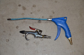
With the brushes out, I took the opportunity to blow more air through the motor.  A lot more air.  The air gun I had been using works fine, but the nozzle is fixed and short.  I bought an air gun with an 8" flexible nozzle that I was able to carefully insert into the motor and spray in harder to reach areas. 


I sprayed compressed air until I saw, or could smell no more dust.  Believe it or not, that dust has a funny smell (even though I was wearing a mask).  I put the new brushes back in carefully, and took another reading with the Ohm meter.  To my astonishment, the leak was actually a bit worse.  I hooked up a 12v battery to the motor with a switch in line so that I could run the motor for a bit and try blowing more air while the motor was moving.  Had to be careful not to stick the nozzle anywhere in the motor or near the brush assembly.  4 or 5 more tanks of air and no dust coming out.  At this point, the motor is as dust free as I can get it without taking it apart. 

After all that, the leak persists.  At it's worse I measured the resistance between the S1 terminal and the case at 508 Ohms.  That's enough to pass 320 milliamps.  Again, not a lot, but certainly enough to feel, and enough to render the charger useless. 

I contacted George with the story, telling him the results of my efforts, and sending him the picture of the brush.  At this point I'm faced with either taking the motor apart and trying to clean it further, or getting a new one.  George was absolutely dumbfounded when he saw that picture.  He said that it looked like someone had tried to make a Brush Wear Indicator, but he couldn't figure out why they drilled three holes, or worse yet, why they left that brush in the motor.  He was pissed, and justifiably so.  He's paid to have this motor repaired twice and the second time he told them to pay particular attention to it so that it was done to the highest standard possible.  Clearly, that didn't happen. 

Fed up with the whole thing, George is sending me a new motor.  I must say, that I have very mixed feelings about this.  On one hand, I'm thrilled to be getting a motor that will hopefully have none of the flaws that have plagued this motor from it's first day.  On the other hand, it just eats me up that this whole fiasco has cost George so much.  Shipping to Illinois and back, twice, two rebuilds of the motor, and finally a whole new motor plus the shipping for that from Illinois.  Dreadful!  I had hoped to be one George's success stories. 

While all of this is going on, I am planning a couple minor enhancements.  I bought a voltage meter/display from Lightobject that can be programmed to cut a relay at a specific voltage.  I'm thinking that I'd like to add that to the car as a safety backup in case the charger doesn't cut off in time.  If this device sees the voltage rise to the level I've defined, it would trigger a relay that would simply cut power to the charger, protecting the batteries.  Stay tuned. 

Friday, February 24, 2012

Brushes and Carbon Dust

While at EVCCON 2011 I had the good fortune to catch a talk given by Tom Brunka from the Helwig Brush Company.  Tom went into great detail about how brushes for DC motors work, the different properties they can posses depending on the way they are manufactured, and the care of brushes and motors.  On the face of it, it seems this talk would be astoundingly boring, and in fact I think Jack Rickard scheduled it for the last talk of the conference precisely because he figured it would be lightly attended and would be in no danger of running long and interfering with the events planned for later that day.  As it turned out, it was a truly fascinating talk and it went much longer than expected due to the fact that attendees started asking questions as soon as Tom finished and simply wouldn't let up.  Eventually Jack had to put a halt to the exchange so that we could all go outside and race our cars.  What a great time that was.

One of the things that Tom mentioned is that brushes will wear and break in at one rate, but once they are bedded in, they will wear at a completely different rate.  The wear of the break-in rate is much higher than standard wear rate.  But the interesting thing is, if you disturb the brushes, i.e. remove and replace them, lift them out of their holder, nudge them, breath on them, or even look at them askance, they will begin to wear at the break-in rate again.  This level of wear has a couple of effects.  First and perhaps most obvious, your brushes wear out faster.  As a direct result of that faster wear rate you encounter the second issue, which is an accumulation of the dust that wore off the brushes on the inside of the motor.  If you have the motor ventilated with forced air, some of that dust will be carried out of the motor's vents.  But not all of it.

Such is what has happened with my motor.  Faithful readers will remember that I have had the motor out of the car a couple of times due to a strange phenomenon where the balancing putty fell off the armature.  On both occasions George Hamstra at Netgain motors, shipped the motor back to Warfield electric and had them repair it.  In order to do so, they had to dis-assemble it.  Now I didn't look at the brushes when the motor came home from the first repair so I don't know if new brushes were installed, but I did look at them the second time and they were the same brushes that were in the motor when it left.  How do I know?  Well new brushes are not contoured to fit perfectly against the armature when they are new.  As I said earlier, they must be worn, or bedded in and this can take up to 5000 miles to do.  But since the brushes had necessarily been removed during the motor's repair, that meant they were going to go through another instance of excessive wear and re-bedding; meaning more dust.

What does this have to do with my current situation?  Well, all that carbon dust is conductive.  After all, it's through that very carbon that the current is pushed to the armature of the motor.  I have a fan on the motor, pushing 110 CFM of air through it and likely carrying out a good percentage of the carbon dust along with the heat it's meant to blow out.  But clearly not all the dust is going out.  Somewhere within the motor, some dust has piled up and allowed a small path for current to flow from the high voltage fields to the case.  That's not good but apparently not unheard of.  Normally, you simply blow the motor out with compressed air and the problem leaves the motor in a plume of black dust.

So, I charged up my compressor, took the shroud for the fan off the front of the motor and started blowing.  There was plenty of dust.  More than I expected.  I thought this was great, it meant I likely fixed the problem.  Unfortunately not.  The problem is that in order to get all the necessary components in the car for it to function, Or simply because I'm very bad at designing things, all the components are crammed in there so tight it's difficult for me to get a nozzle in there to blow out every nook and cranny.  But my blow gun's nozzle is right at the end of the trigger limiting where I can really point it.

I've exchanged some emails with George and he suspects that the brushes in the motor right now are a high performance brush called H49 which do great for racing, but tend to dust a lot.  He thinks that the H60 brushes, which are a harder, street grade brush would be better suited for my build with the added benefit that they will produce less dust.  He's decided to send me a set of these at no expense.  Well, no expense to me.  They normally run over $300 a set and George is picking up the bill.  To say that George is fed up with my motor is an understatement.  He's stated that he will not RMA the motor again.  Meaning, if it ever has another problem, he intends to replace it.  Believe me when I say that it's very comforting knowing that he will stand behind the motor so resolutely.  For now, I just don't see a reason to do that, and here's why.

The new brushes will arrive early next week.  I've ordered a blow gun for my compressor with a 12" flexible hose which will allow me to better squirt air in all the nooks and crannies inside the motor.  I'll remove the old brushes, and push 8 or 10 tanks of air through the motor, then replace the brushes.  If all goes well, I should see the short go away.  Depending on the temperature, and consequently the time of day, the resistance of that short fluctuates between 1.18K Ohms, and .85K Ohms.  That means a potential leak of current in the range of 135 to 188 milliamps.  If I can't resolve the short and I have to take the motor out of the car then I'll have to decide whether I want to try to disassemble it to clean it, or simply give George the go-ahead to send out a replacement.  I really don't want to do that though.

Friday, February 10, 2012

Battling a Frame Leak

This is a god-awful long, and most likely boring story.  Once again I'm hoping I can serve as an example to all you fine readers,  for what not to do.

About two weeks ago I pulled the Z3 into the garage and plugged it in.  When I flipped on the charger I heard, what sounded like, a popping noise coming from the front of the car.  It sounded like the noise you hear when you plug a speakers into the audio port on your computer, deep and quick.  But there were some kids playing out front and I wasn't sure exactly where the noise came from.  But the charger continued to charge and everything on the car checked out.

The following day I went to plug it in after another day's driving and I listened closely, this time with the garage door closed and the hood up.  Sure enough, I heard the same pop, only this time the charger turned itself off.  You may remember about a year and half ago, I was measuring one of the batteries during a charging cycle when one of the probes slipped and made contact with the chassis and the terminal at the same time.  There was a pop, the end of my probe was vaporized, the charger shut off and the breaker for the 240 volt AC outlet tripped.  That little mistake cost me $150 because I had to send the charger back to Manzanita to repair the AC rectifier which I blew up in the process.

After this recent pop I figured 1. I must have a high voltage leak to ground and 2. I'm going to have to send my charger along with another $150 to Manzanita.  I decided to check for the leak and got out my multimeter.  Sure enough, if I measured at the most positive terminal on the battery pack, and the chassis, I could measure the full 160 volts of the pack.  Damn!  I went to the fourth battery from the end of the pack and measured there and got the expected 13.2 volts.  I wondered how much current could get through this leak, so I clipped a regular automotive tail light bulb to the positive terminal of that battery and the chassis and it glowed nice and bright.  If there were no leak, or no path for current, that bulb would not light up.

OK, it was time to start disconnecting things to isolate where the leak was.  This should be a pretty straight forward task, and it seemed to be at first, but it wasn't long before it got weird.  I'll explain.  I started by unhooking all the peripherals, one by one, using the multimeter after each to see if I had voltage to ground.  I disconnected the DC to DC converter, the charger, the Masterflux A/C system, the ceramic heating element and finally the Link-Pro meter.  By this time only thing hooked to the high voltage system where the Zilla controller, the motor and the batteries them selves, but still the leak was present.  I unhooked the cables leading from the Zilla to the motor and the leak was gone.  Ah ha, found it!

My guess was that through poor design, I'd placed a cable close to something sharp and it had rubbed through and shorted to the chassis.  In deed, I found what looked like a suspicious wear mark on top of one of the rubber boots, under which is one of the terminals of the motor.  But as it happened, it had not worn through, though it would have eventually.  But then I noticed that I'd done something else that was remarkably stupid.  The main high voltage fuse of the car, which is held in a special holder which does not keep the fuse from sort of sliding one direction or another, had migrated one direction and looked like it was touching a part of the chassis.  Well, there you go!!!

I fixed that problem and insulated the connection so that it can creep all it wants and will never short against anything again.  I checked all the other cables and connections and found them good, so I started putting everything together.  I got everything back together, put the multimeter on the car and... I could still read the pack voltage.  Ah crap!  But this time, there was an important difference.  When I performed the light bulb test, there was not enough current flowing through the chassis to make the bulb light up.  At this point, I'm thinking there must have been two leaks.  I'm assuming I fixed the more serious one, but there's still a smaller one.

Now's where things get strange.  I started testing again, trying to be as methodical as possible, but I kept getting strange results, or results I didn't expect and couldn't explain.  For a while I was certain there was a leak through the Zilla, but that wasn't the case.  You see the problem is that I've run up to the end of my knowledge at this point.  When it comes to electrical stuff and electronics, if I can't SEE it, I'm probably not going to understand it.  I can SEE a wire touching the frame.  But once that wire enters a device, as far as I'm concerned what goes on in there is simply magic.

I'll save you some of the wretched details, but suffice it to say after disconnecting everything one at a time, again, I was left with only the batteries connected to the Zilla and I still had a leak.  But then I saw that I still had the current sensing leads from the Link-Pro connected to the shunt.  I thought well that can't be the problem, but I'll disconnect them to be sure.  Lo and behold, the leak went away.  What the hell!!  Maybe that line got pinched or abraded.  Nope, it looked fine.  The meter is supposed to be completely isolated from the chassis because I've used an isolating DC to DC converter specifically to power the meter.  I measured the 12 V output of that DC to DC converter and found that I could read 12 Volts if I grounded to the chassis.  Well that's not supposed to happen!  There's my problem!!  Or so I thought.

I started putting everything back together, one thing at a time, taking measurements with each connection made.  For kicks I connected the Link-Pro's shunt lines, expecting to see the leak and it wasn't there.  Ah, for crying out loud!  In fact, I measured the output of the Link-Pro's DC to DC converter power supply and it now no longer has any connection to ground.  Still scratching my head, wondering what the hell is going on, I connect the motor back up and the leak reappears.  Right about now, I'm prepared to burn the car to the ground and walk away.

Ignoring the Link-Pro issues for now, I focus on the motor.  I took the Zilla out of the loop and had simply a small pack of 12 cells and the motor ready for testing.  I hooked the negative line from the battery to the negative input of the motor, which happens to be labeled 'A1'.  Then I put the multimeter on the positive end of the battery and the car's chassis and I could read the battery's voltage.  That means there is a path for current from the battery, through the motor, into the chassis and back to the battery.  I measured the resistance and found that it was 1.19K ohms.  Now that's not much, and if I plug that into an Ohm's law calculator taking into account the full 160V pack voltage, that means that leak can pass only 0.135 amps, or 135 milliamps. 

I don't think that's normal.  I believe that the high voltage fields are supposed to be completely isolated from the case of the motor, but I could be wrong.  I know that leak hasn't existed in the past.  Truth is, I have no idea what might cause that, but I have emails in to some experts who hopefully will help me with that.

The good news through all this is that at one point I had the battery pack isolated from everything else and was able to connect just the charger to it.  I crossed my fingers and threw the switch.  It came on, stayed on and was charging the batteries perfectly.  No need for repairs there.

As for the Link-Pro and it's DC to DC converter, I have no idea why it would pass through the high voltage at one point and not another.  I'm wondering if that little converter has capacitors that were storing the power.  I really have no idea.  Again, as far as I'm concerned, that thing is magic.  But I did order a replacement DC to DC converter for a whopping $8.50 that I'll keep handy in case I need to swap out the other one.

If you made it though this and are still awake, congratulations!  If you have any words of wisdom you'd like to share or guidance to offer, I'm keen to hear it.  Just leave it in the comments.